FilaWinder

EDIT-  The FilaWinder is available now as a kit at http://www.Filastruder.com.  The current assembly and operation instructions are posted here.


Here are mechanical assembly instructions for the FilaWinder, on Thingiverse.  The BOM, STLs, board files, schematic files and more are available there.

IMG_5641 IMG_5642
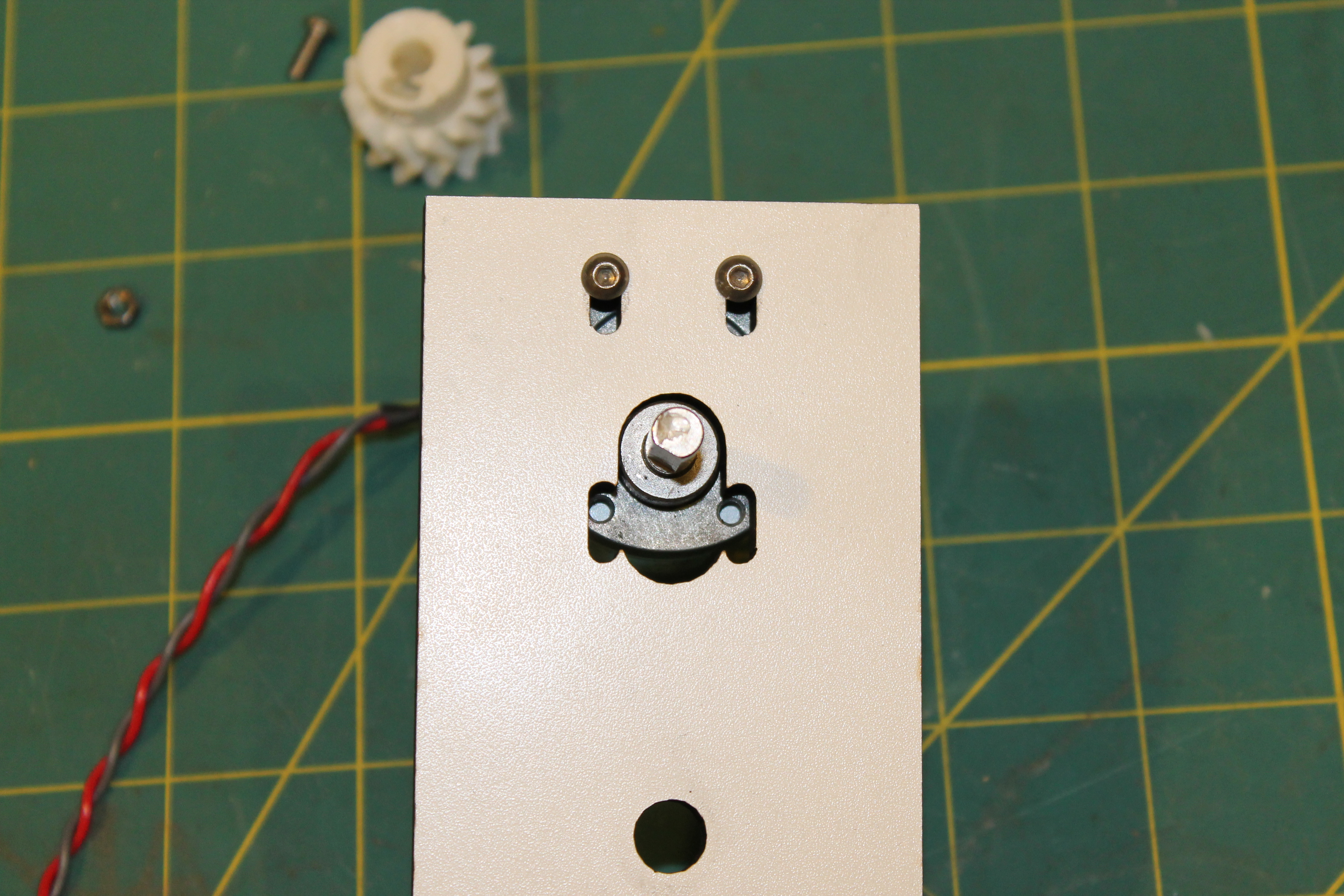
Use 2 M3x12 to mount the gear motor in the slots at the top of the long piece of wood.  Leave them just loose enough to slide the motor up and down.

IMG_5645

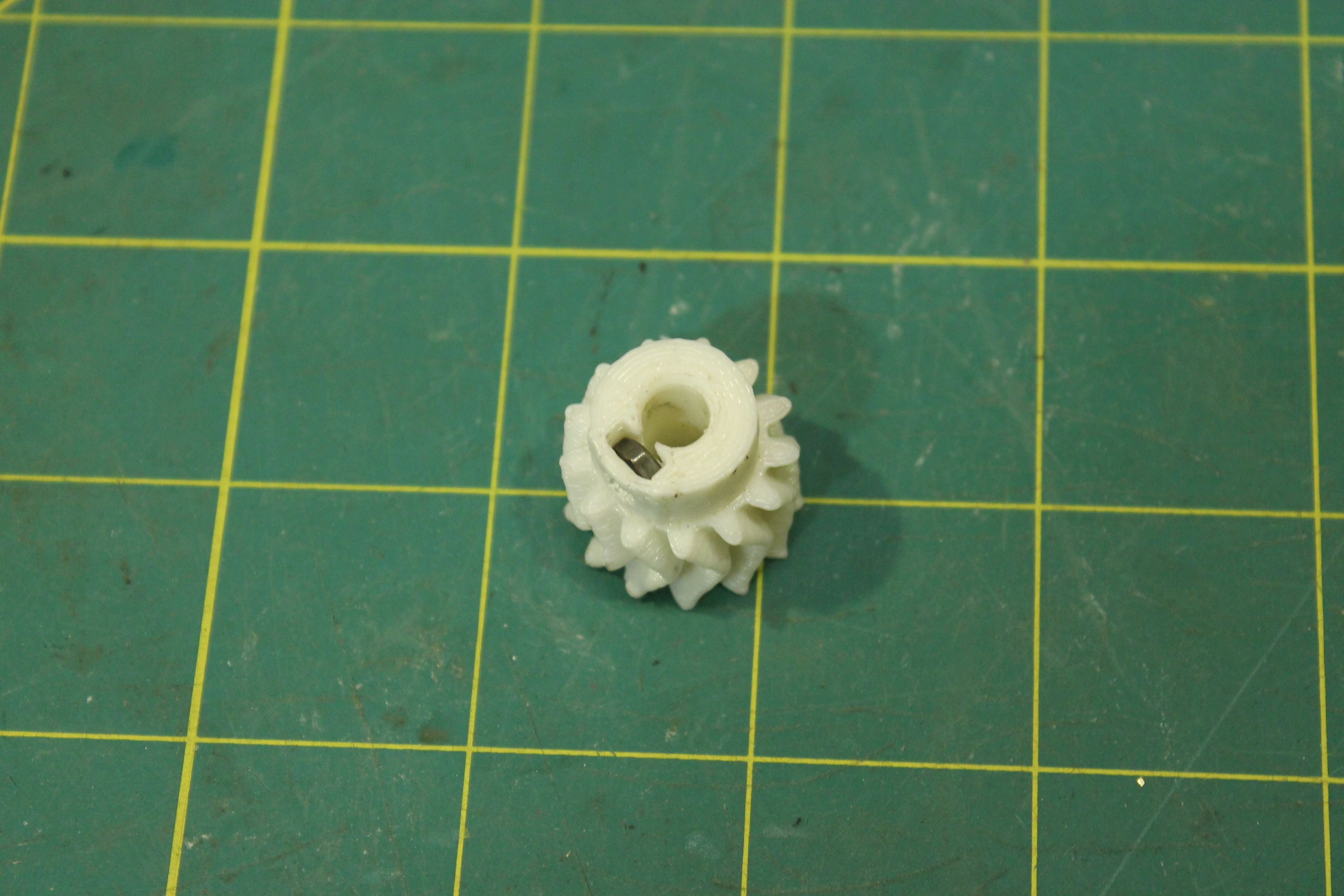
Slide a M3 nut into the nut trap in the drive gear.

IMG_5646

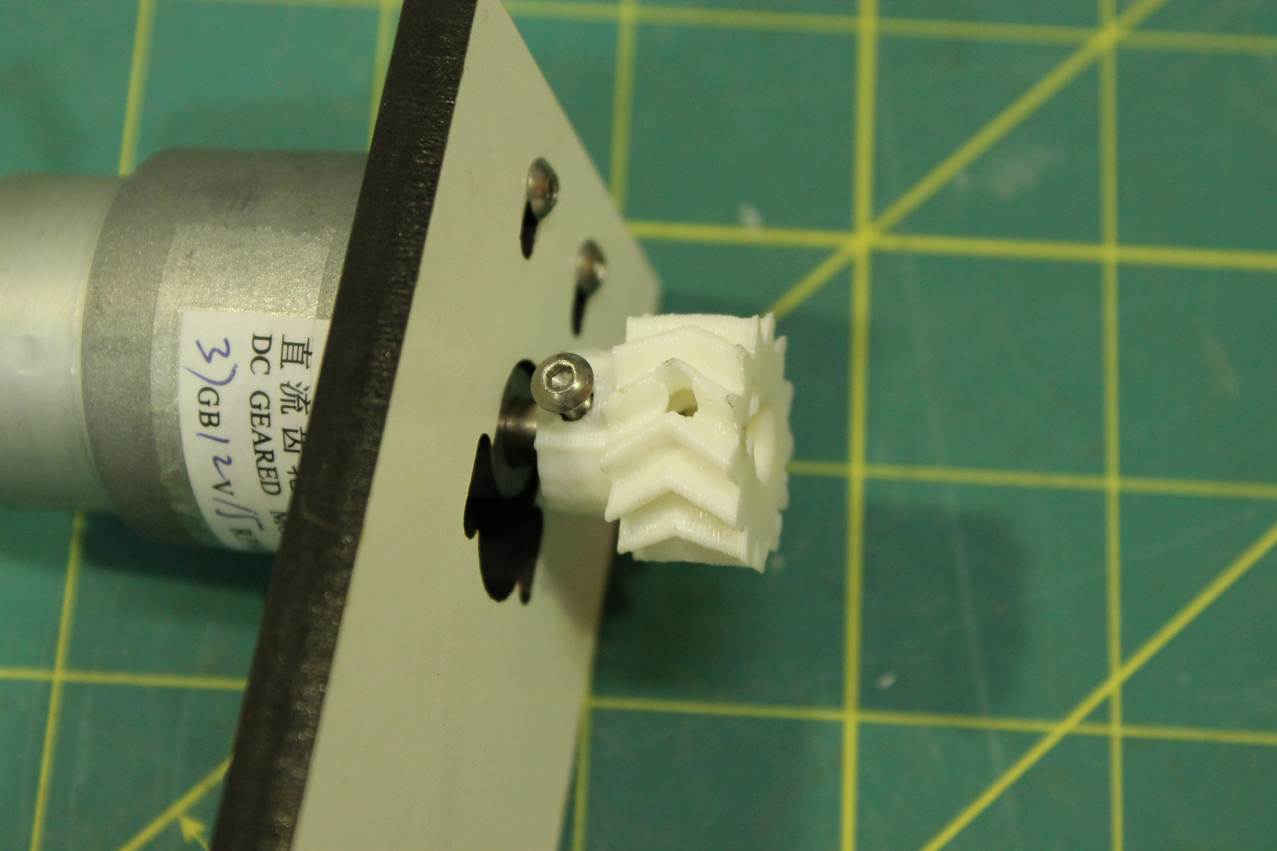
Put the drive gear on the motor shaft and screw the third M3x12 through the nut to hold it tight on the shaft.

IMG_5647

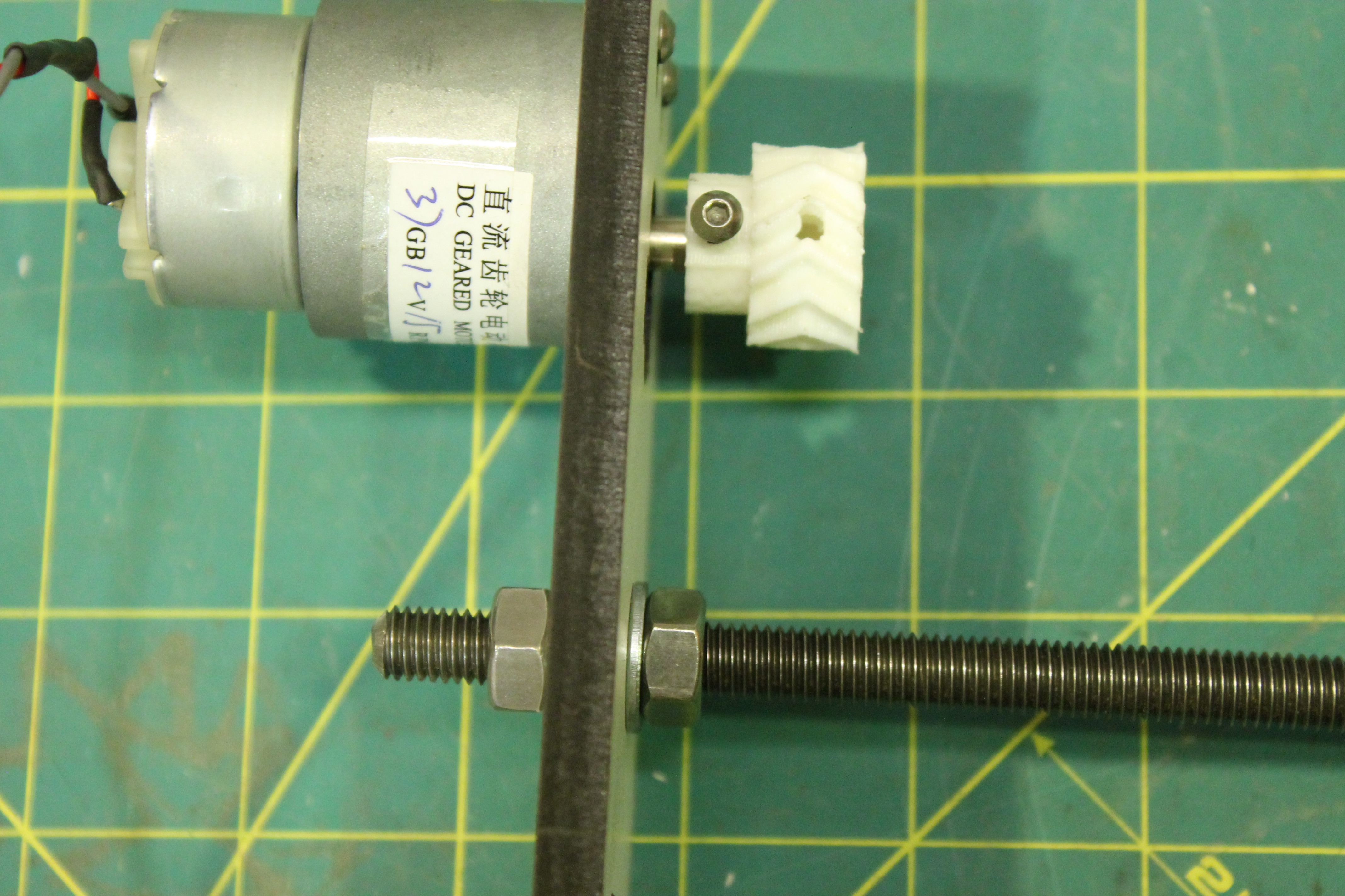
Put the threaded rod through the hole under the motor with a nut and a washer on each side.

IMG_5648

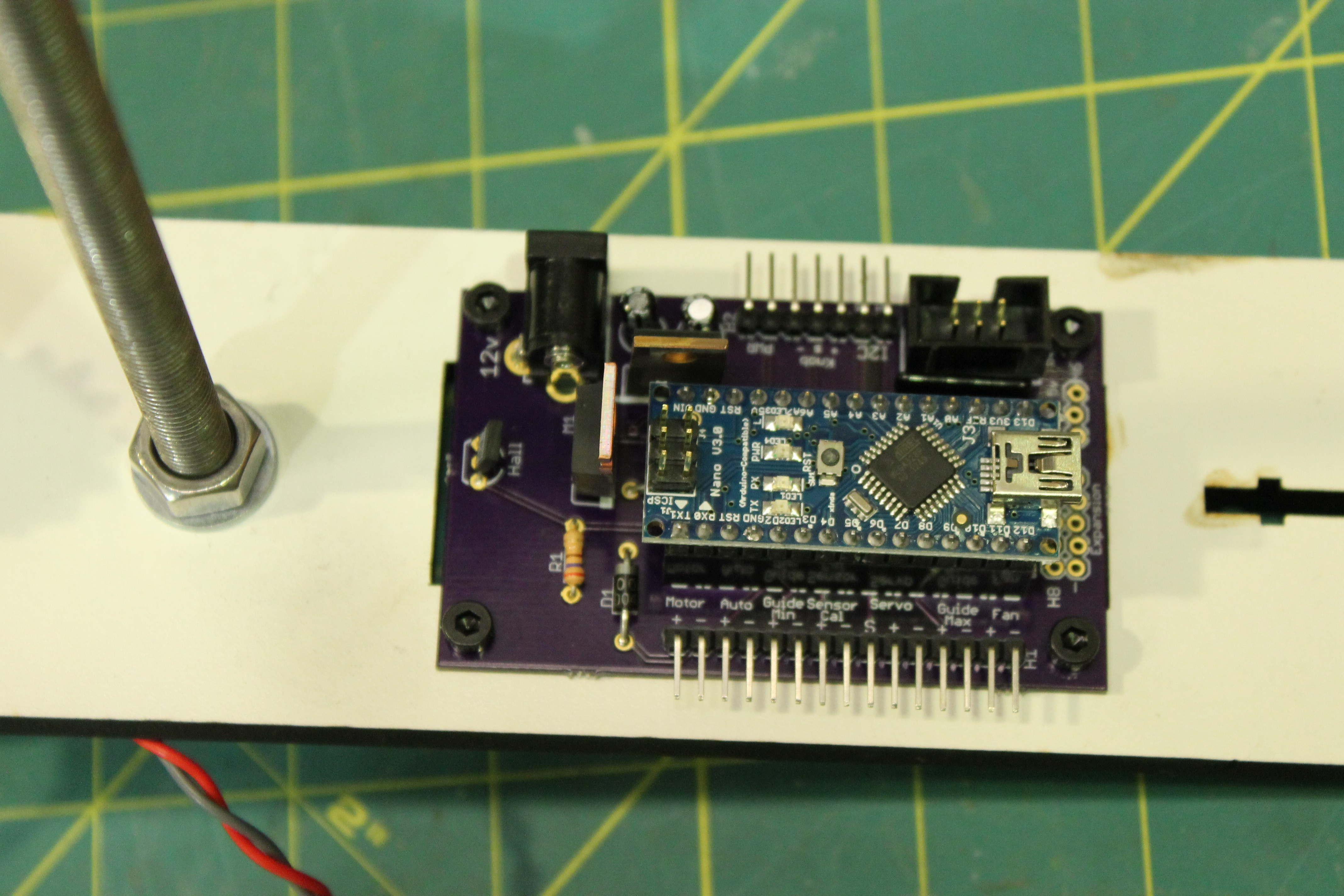
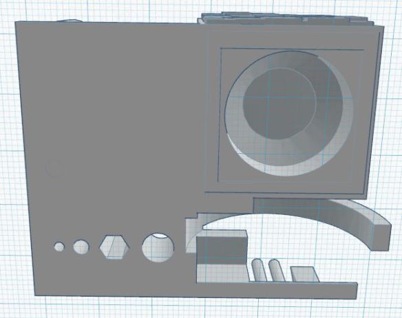
Bolt the electronics directly to the wood with 4 M3x16 screws.  The USB port should be at the bottom.

IMG_5649

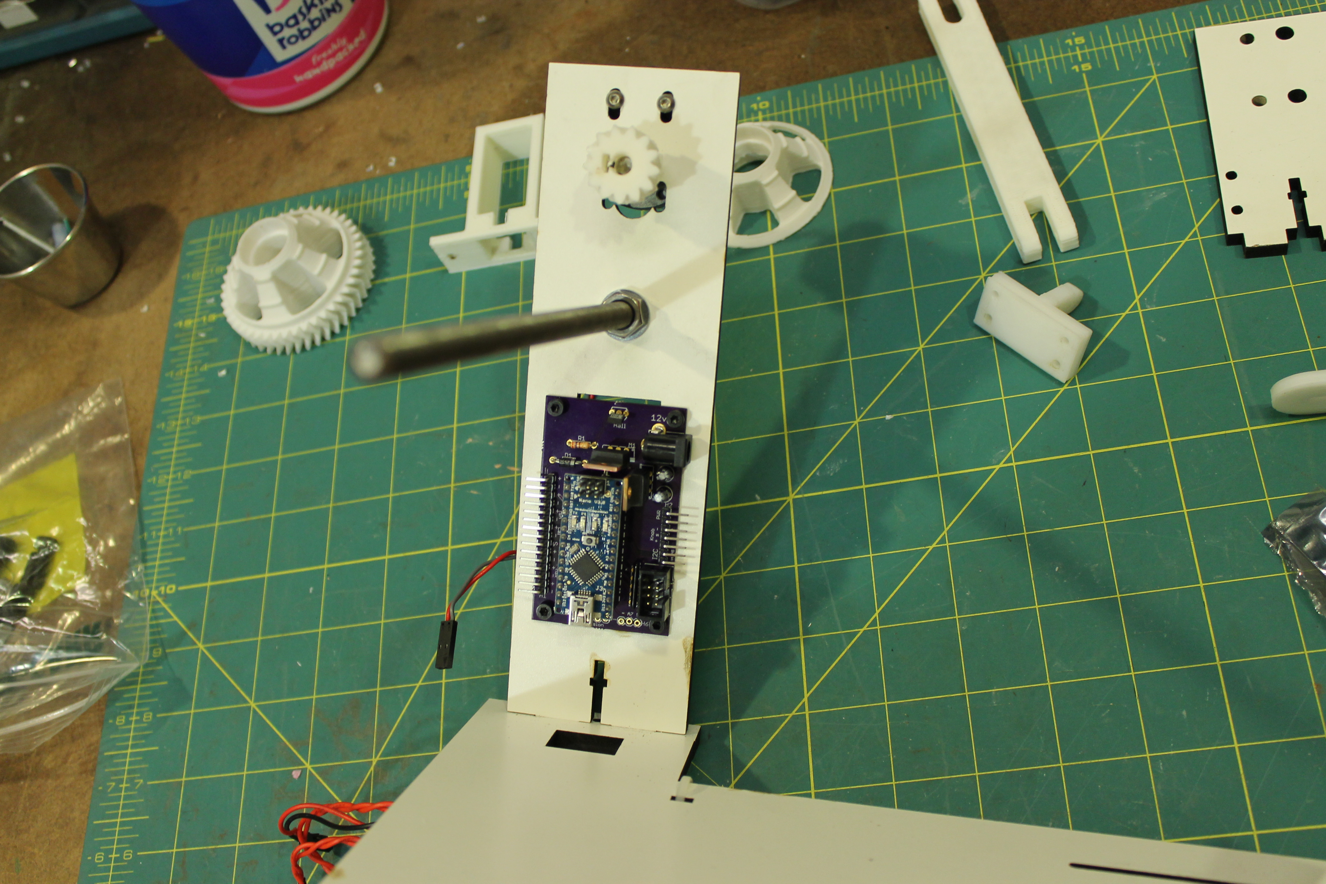
Set the wood into the slots at the back of the base.IMG_5650

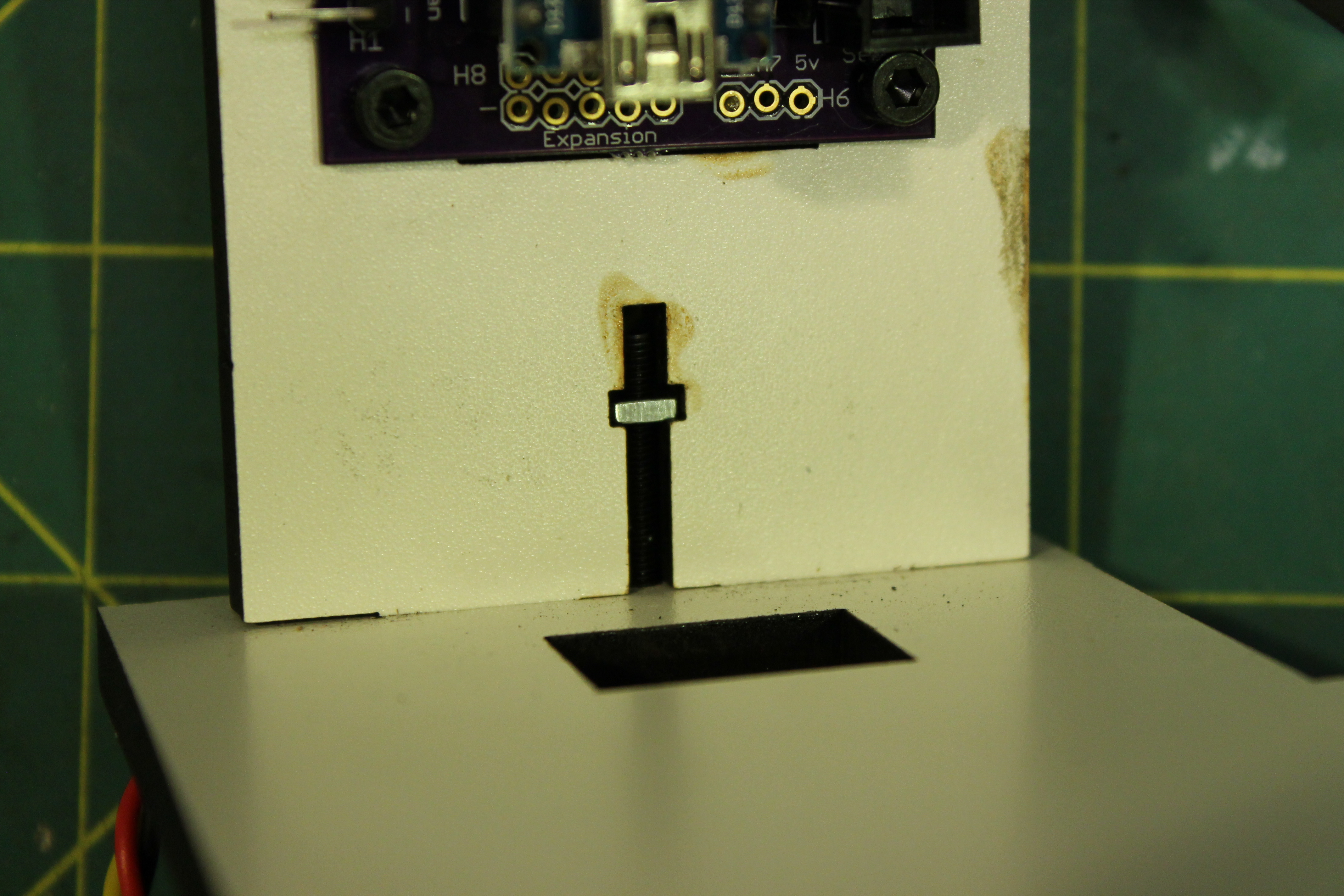
Use a M3x25 bolt and a square washer in the t-slot to hold the pieces of wood tightly together.

IMG_5652

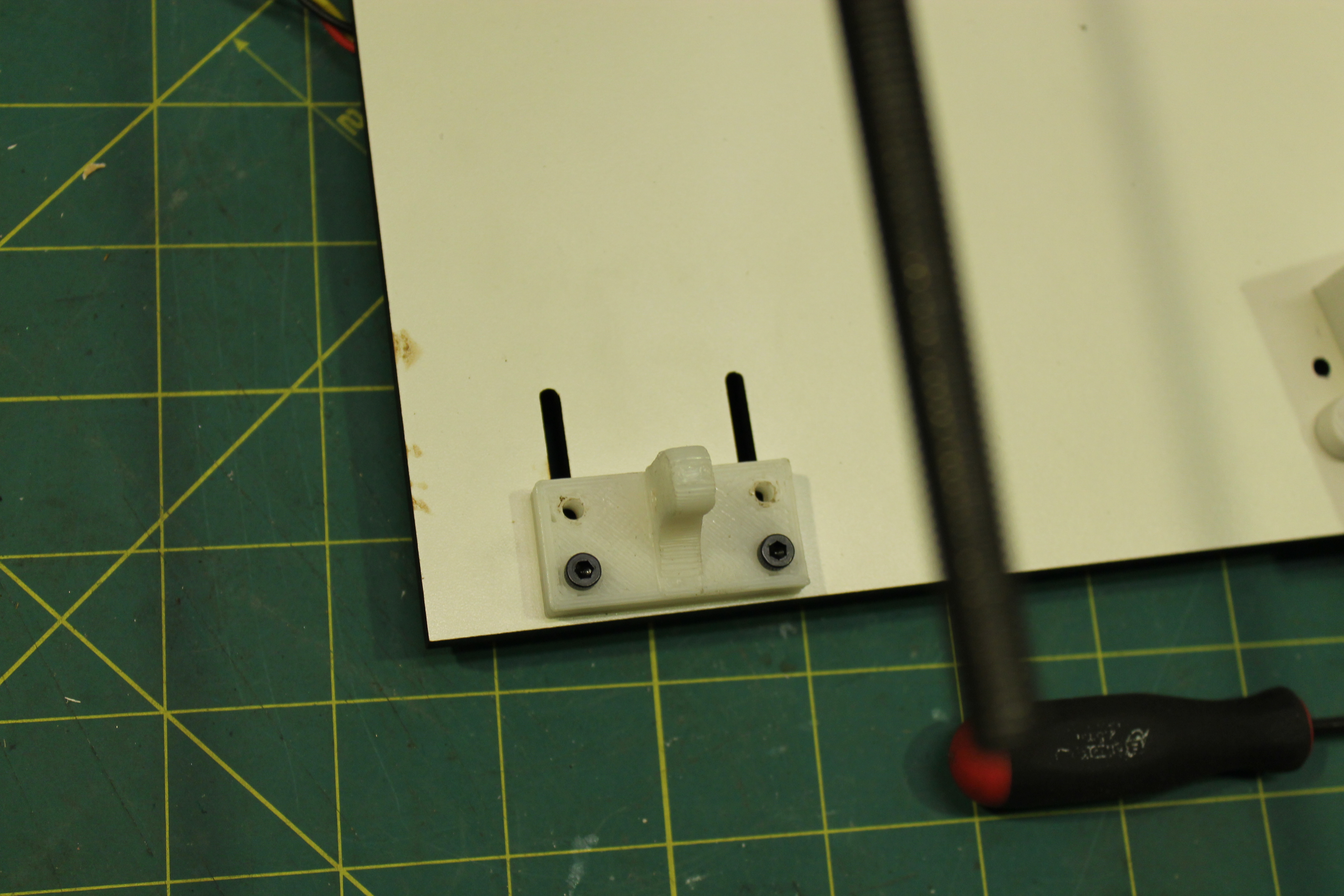
Use 2 M3x16 screws to mount the support base in the slots across from the motor mount.

IMG_5653

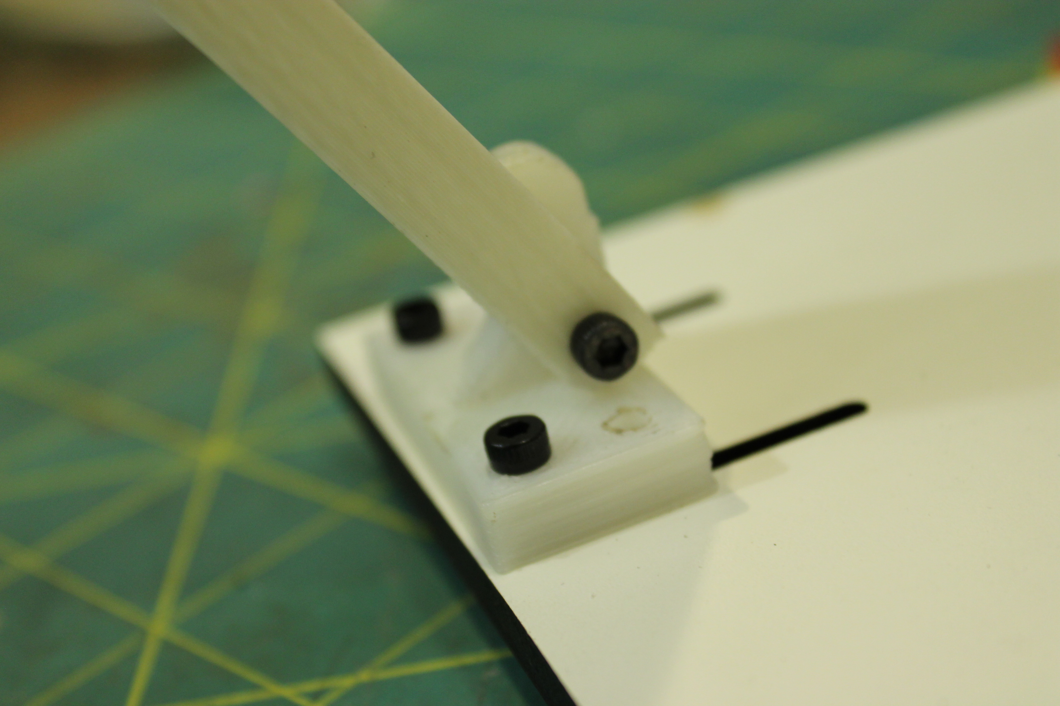
Use a M3x25 screw to attach the support arm to the hinge.  Make sure the curved edge of the arm faces the edge of the board so the arm is free to rotate away from the spool.

IMG_5654 IMG_5655

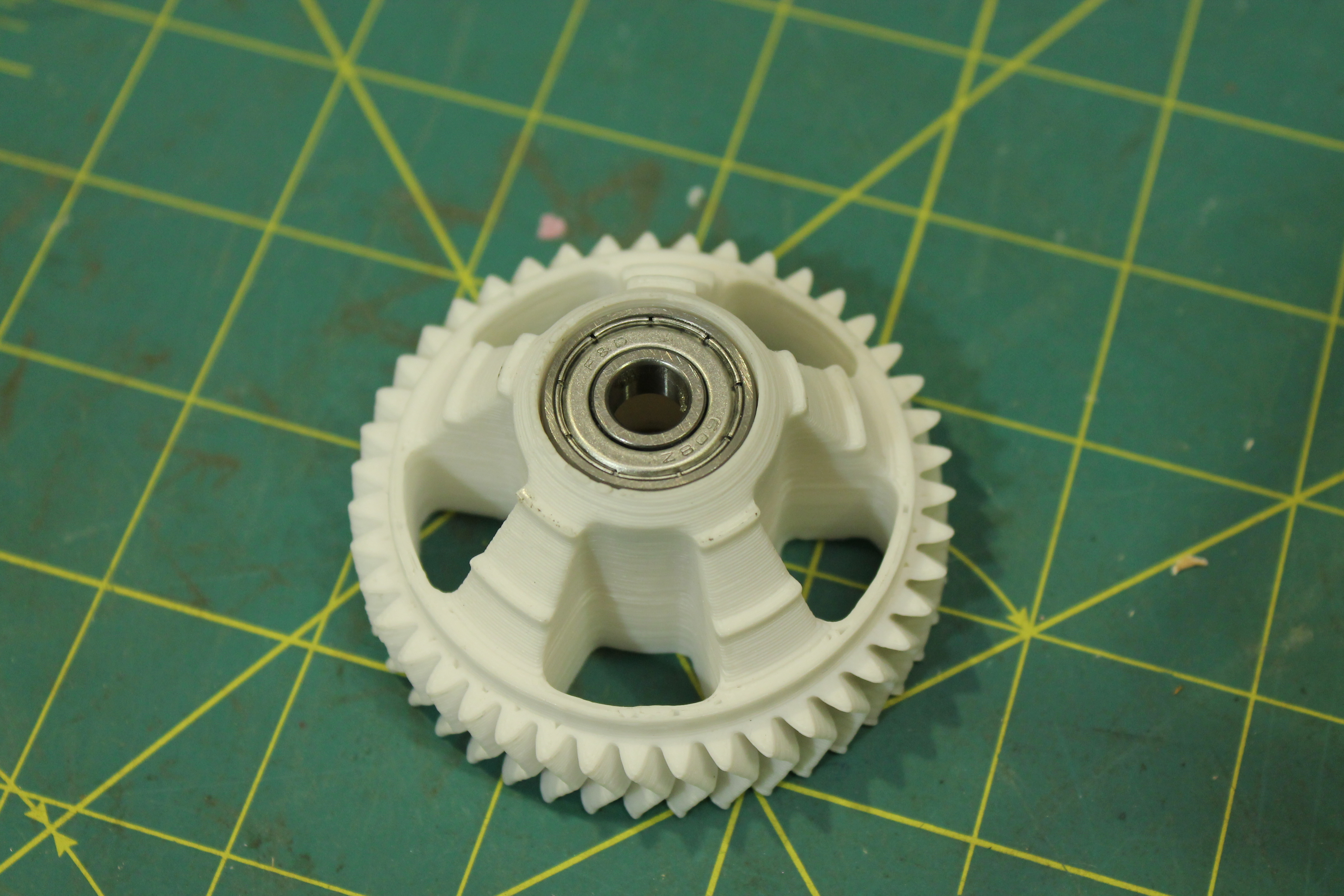
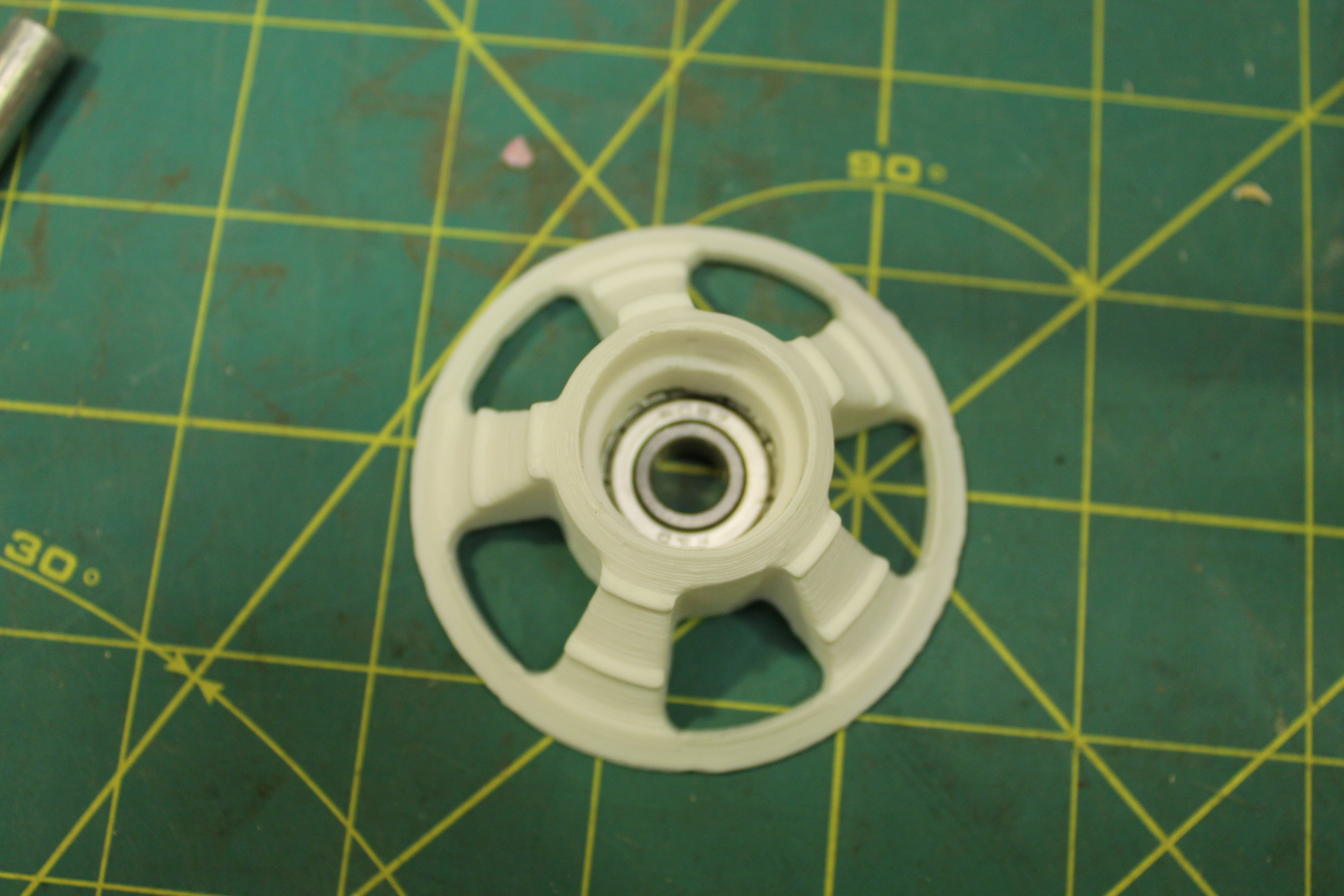
Put a 608 bearing into both sides of the large gear.

IMG_5656

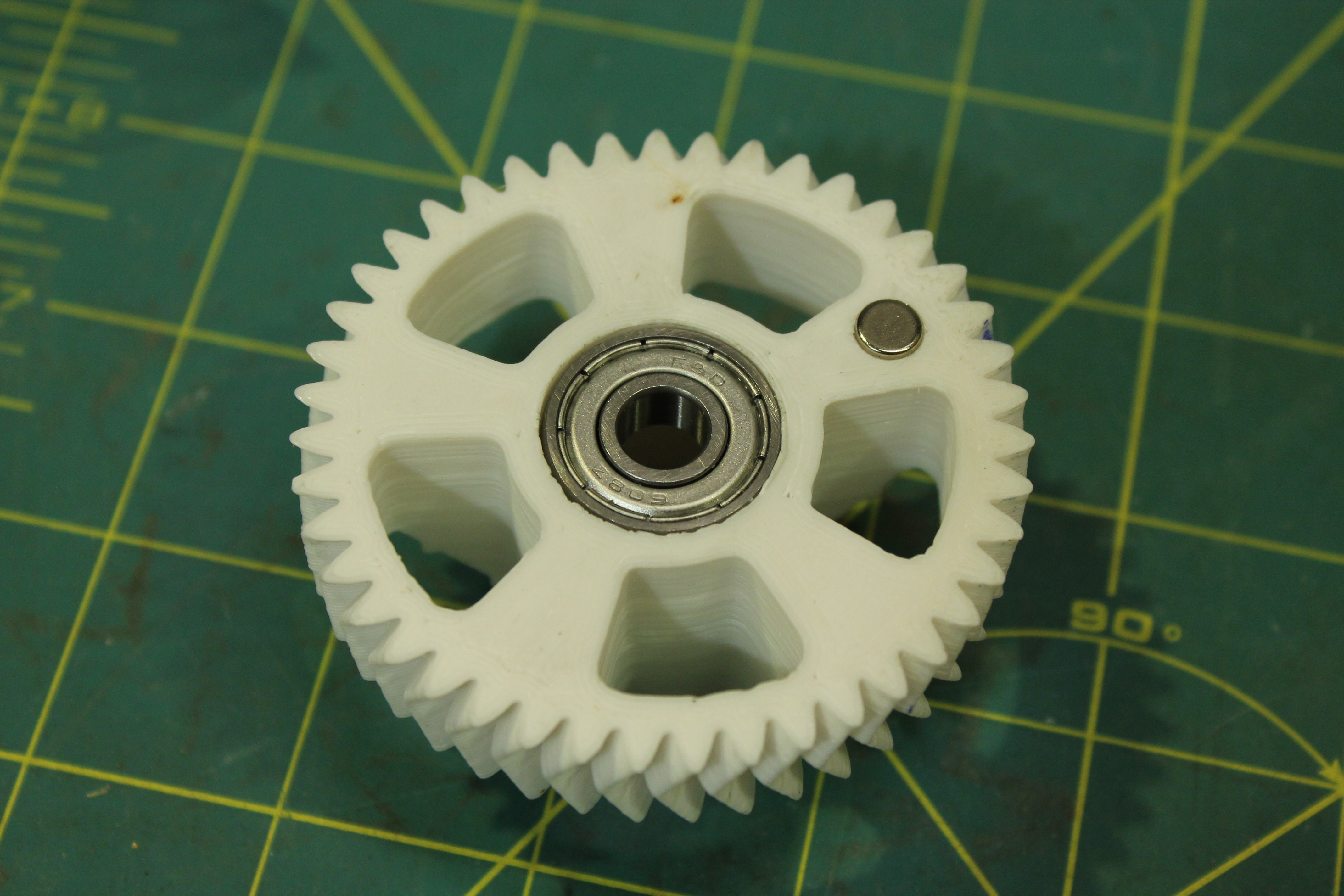
In addition to the bearing, put the magnet into the 1/4″ hole on the flat side of the large gear.  The north pole of the magnet should face out.  If you leave the magnet on its side on a table and flick it a couple of times, it will spin and stop with the north pole facing to the north.

IMG_5657

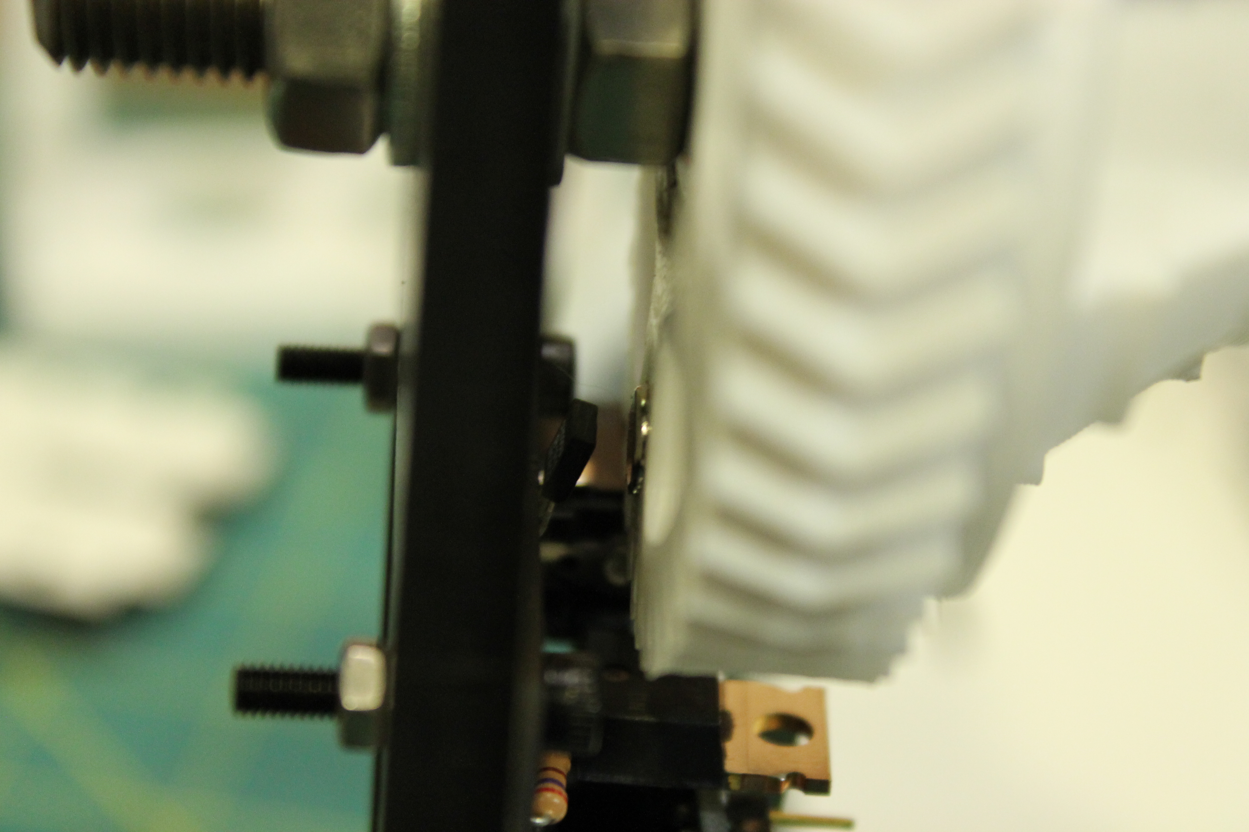
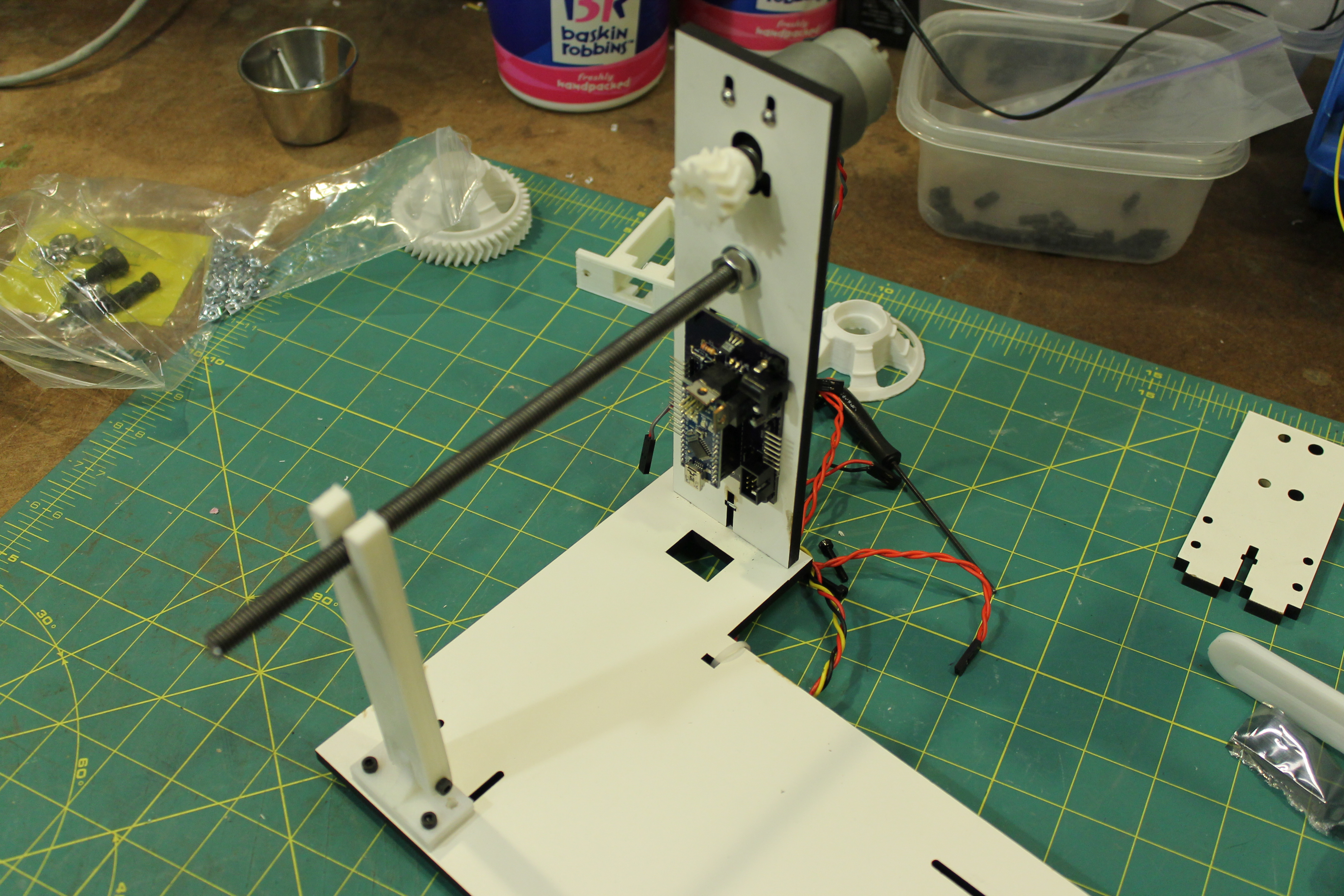
Lift the motor to the top of its mounting slots to move the drive out of the way, then slide the large gear on to the threaded rod.  The magnet should pass close to the hall sensor when you turn the gear.

IMG_5658

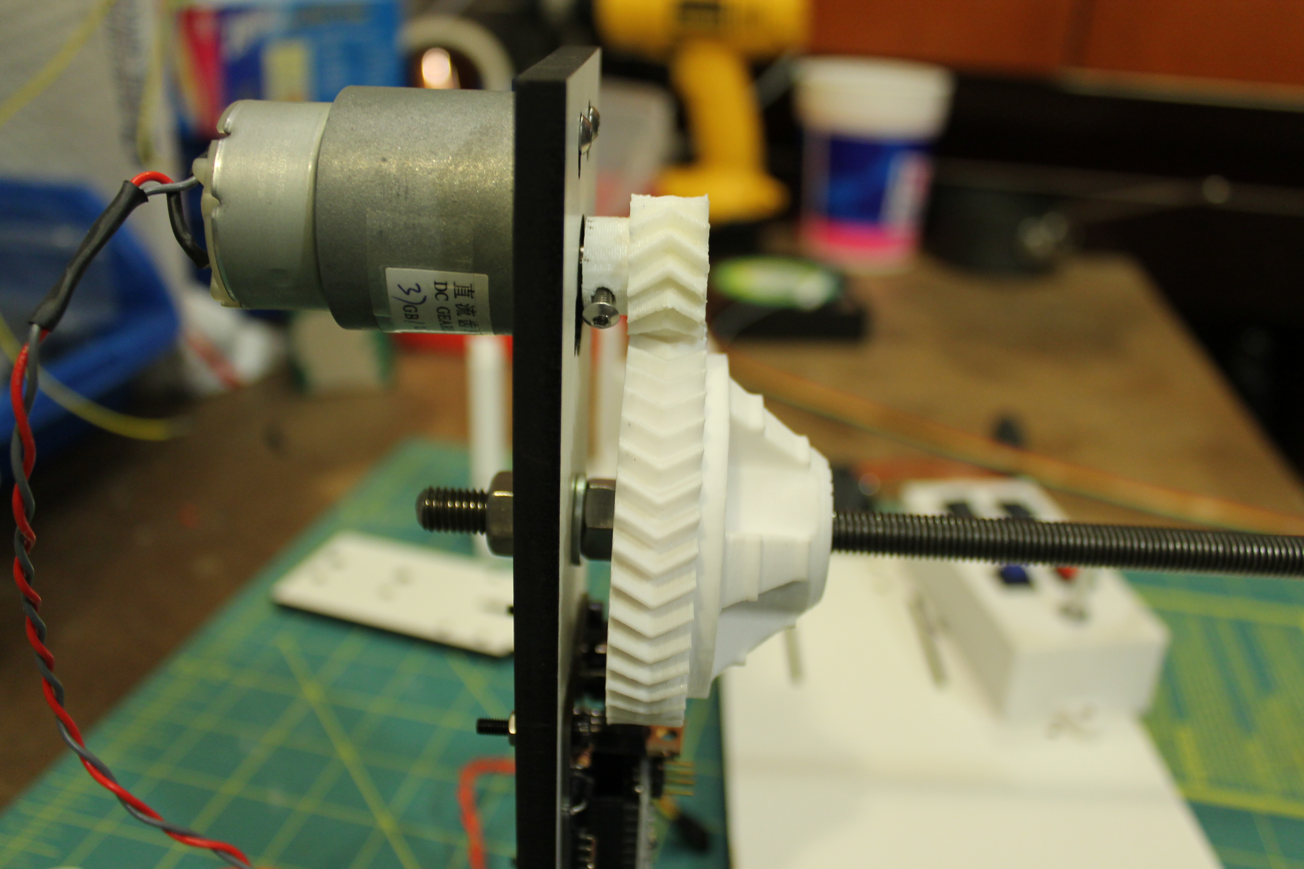
Loosen the set screw in the drive gear and adjust its position until it lines up with the large gear. 

IMG_5659

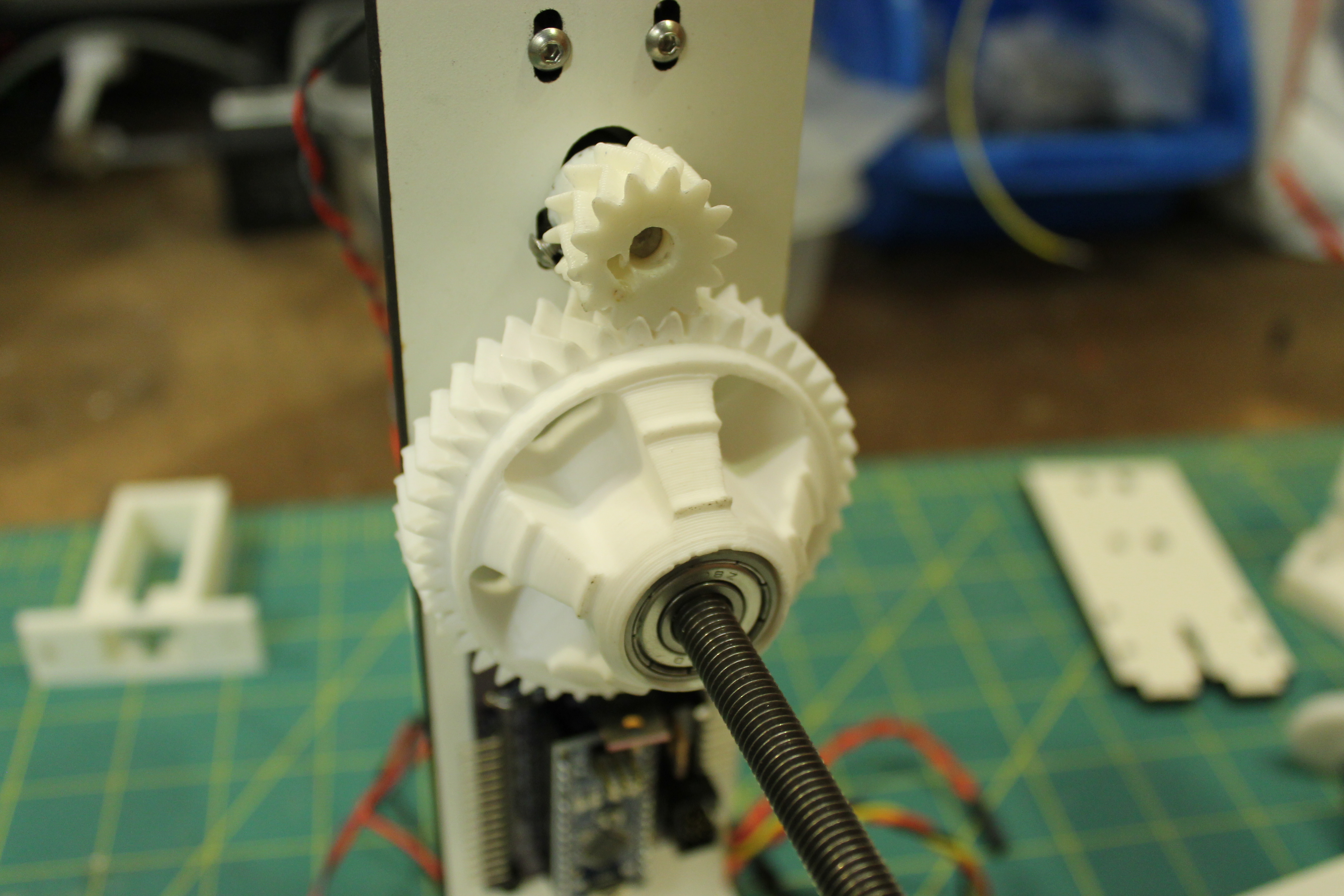
Slide the motor down until the drive gear fully engages the large gear, then tighten the bolts in the slots.

IMG_5661

Put a 608 bearing into the flat side of the spool hub.

IMG_5662

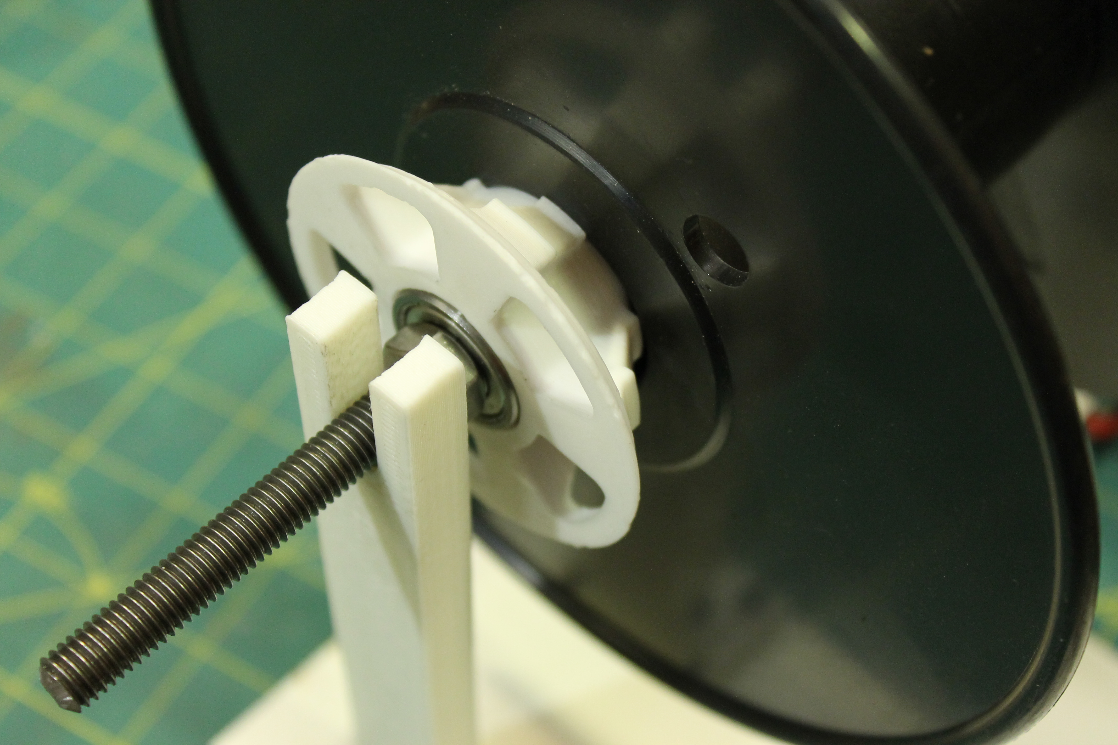
Slide a spool on to the threaded rod and use the spool hub to hold it tight against the large gear.  Tighten a nut against the spool bearing to hold it in placeIMG_5663 IMG_5664

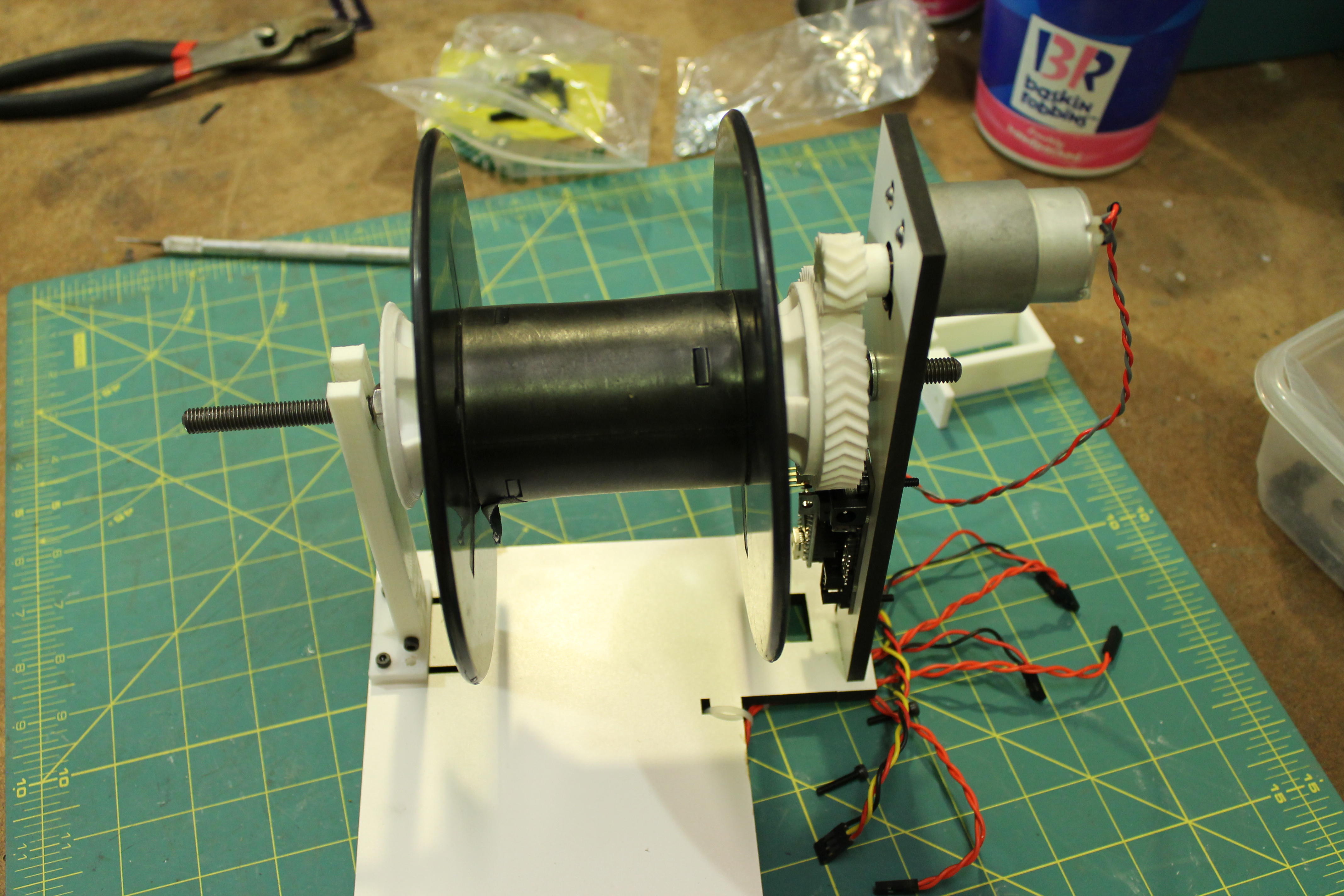
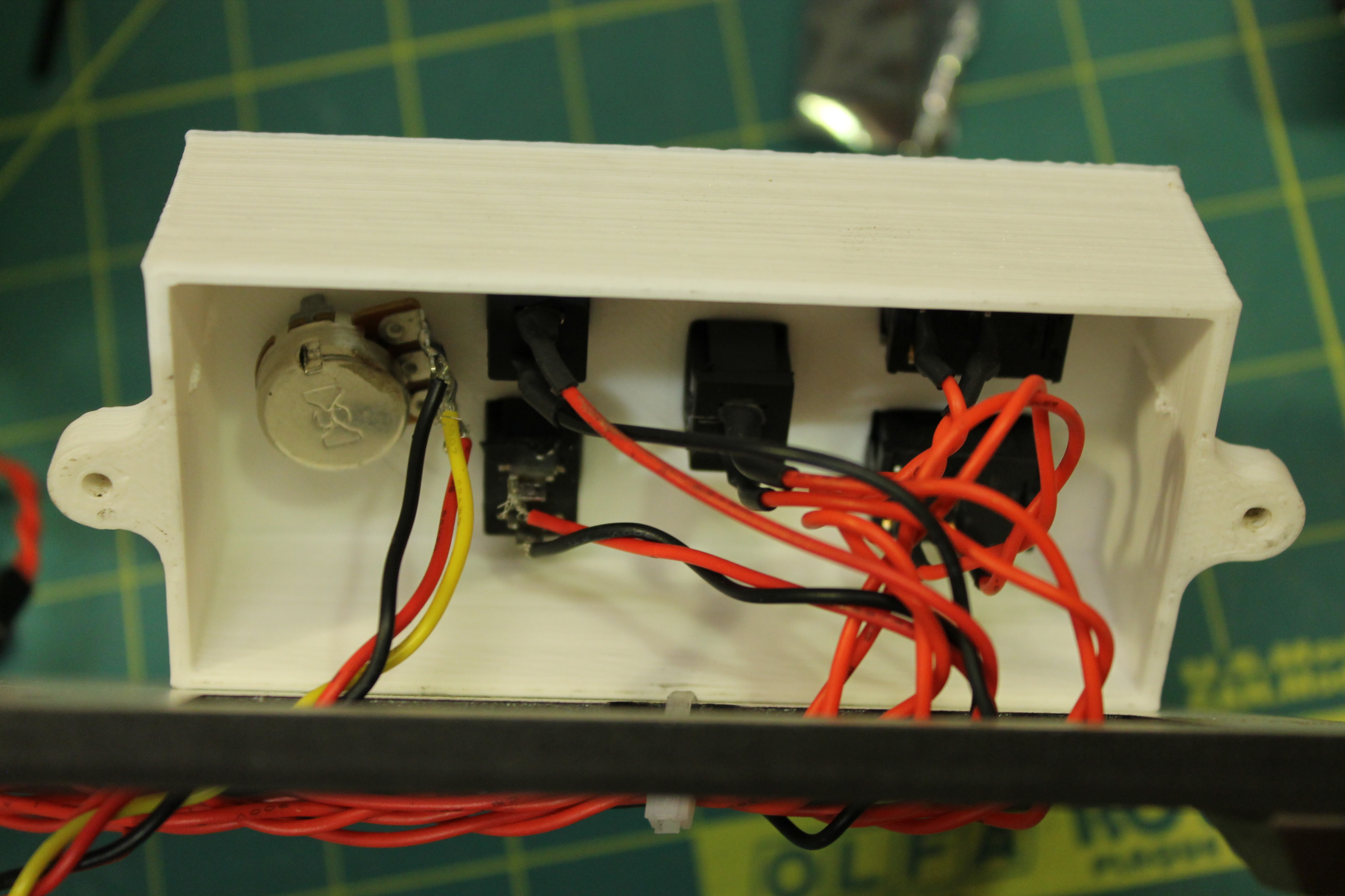
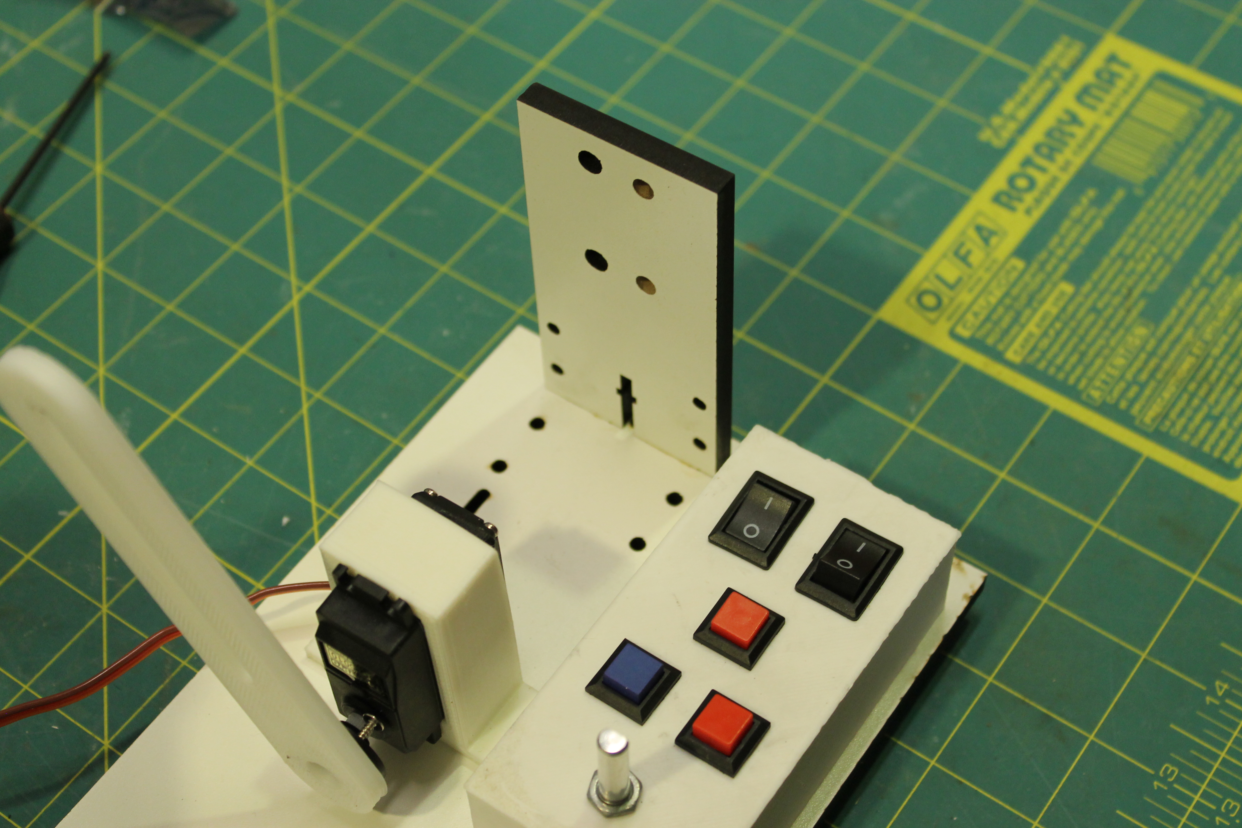
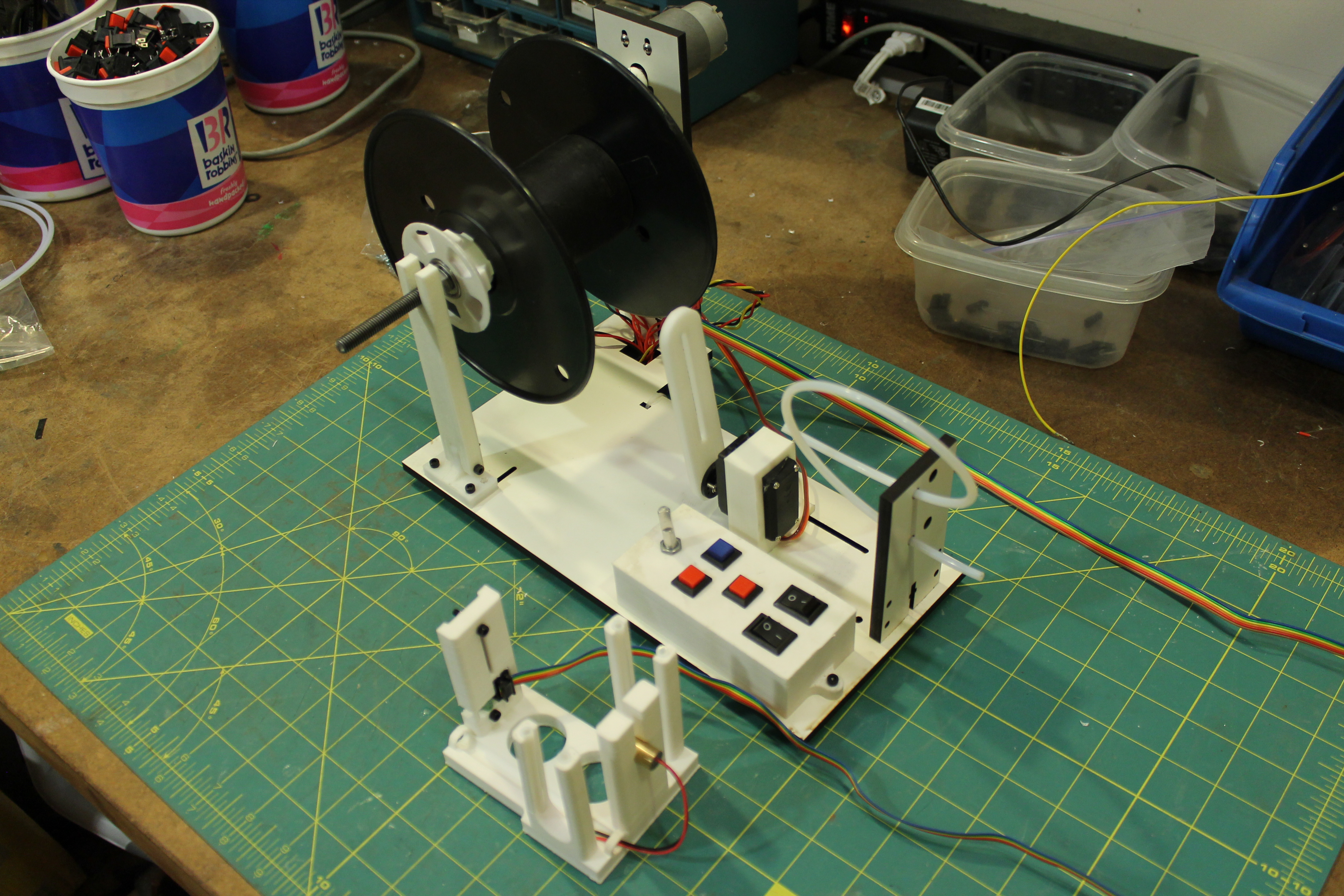
Each of the wires has a crimp at each end.  Cut the wires in half, strip the cut ends, and solder them to the terminals of the potentiometer, buttons, and switches.  Push the crimped ends into the 2×1 housings for the switches and buttons, and into the 3×1 housing for the potentiometer.  Snap the buttons and switches into the control box and mount the potentiometer using the thin hex nut on the shaft.  Mount the control box to the left edge of the base using M3x16 screws.  The wires can run through the hole under the control box, under the base, and up through the hole below the control board.  There is also a notch in the hole under the control box that would allow the wires to run out over the top of the base if that is preferred.  There is a hole in the base near the right edge near the board that holds the motor.  This can be used as a place to run a zip tie to hold the bundled wires against the base.

IMG_5669

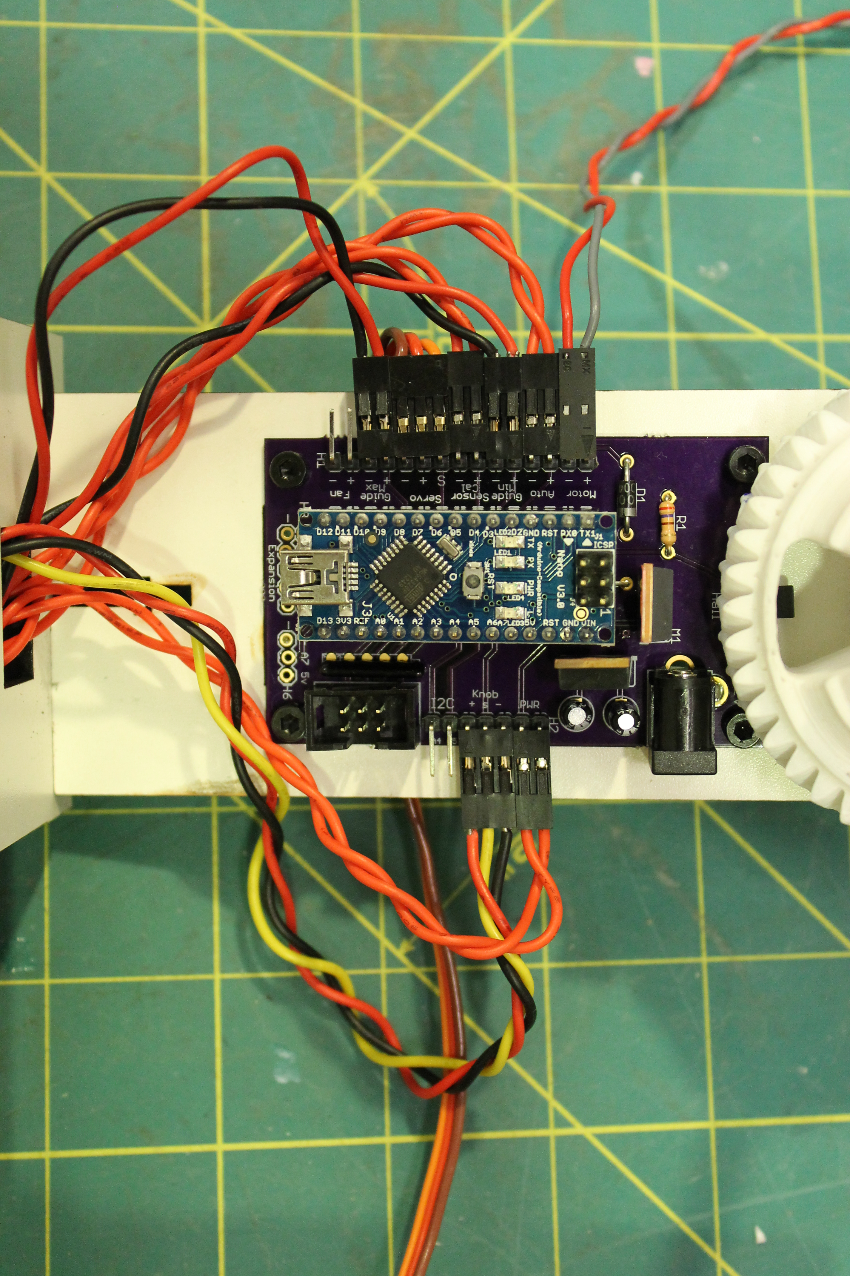
Plug the wires for the right button into Guide Min, the left button into Guide Max, and the center button into Sensor Calon the left edge of the control board.  The wire from the left switch goes into Auto on the left side of the board, and the right switch goes to Power on the right side of the board.  Plug the potentiometer in to Knob on the right side of the board.  Solder a shorter pair of wires to the motor and push the crimps into a 2×1 housing, then plug it into the Motor headers at the top left of the board.  To change the direction of the motor, flip the plug over.

IMG_5665

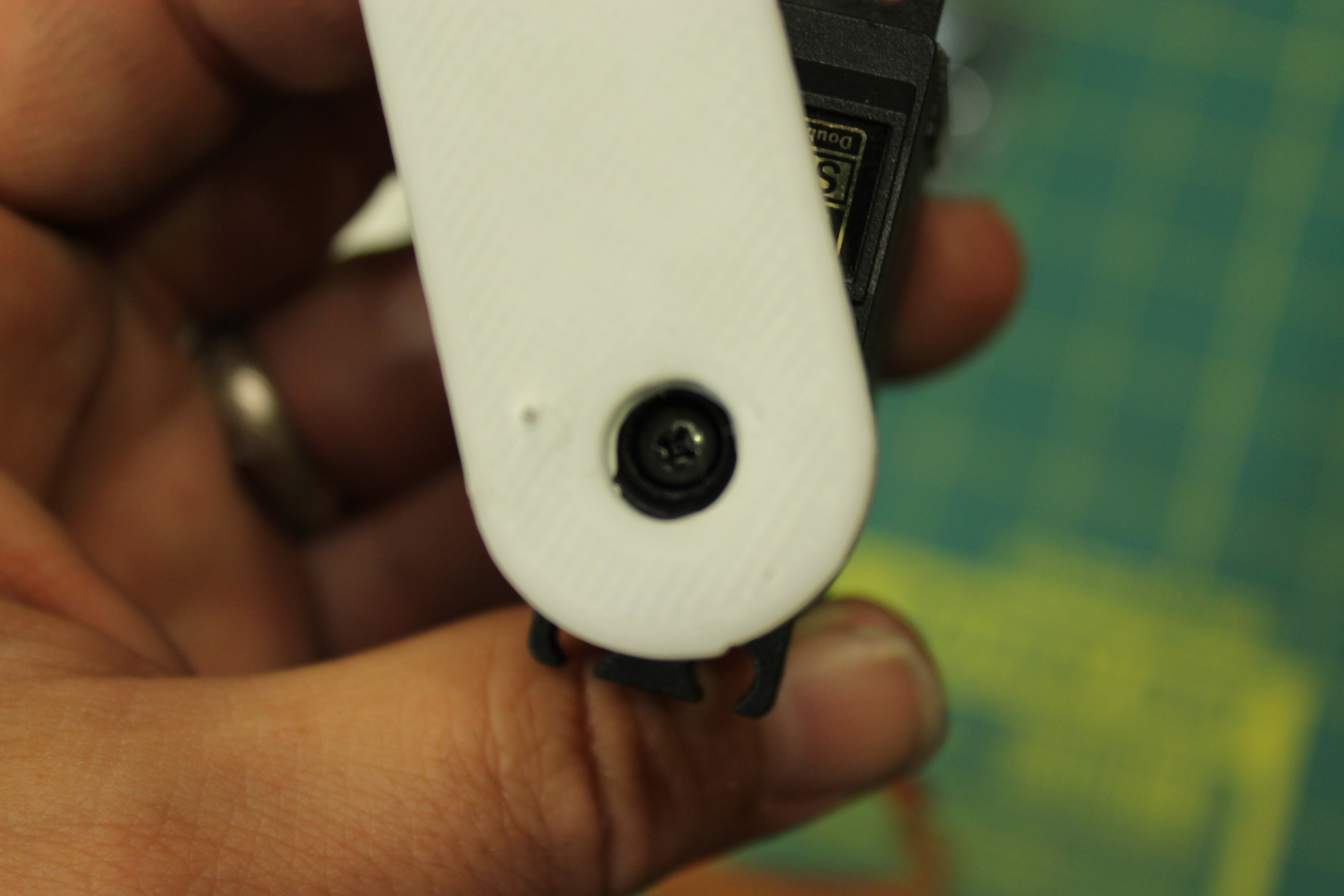
Use the small sharp screws that come with the servo to attach the guide arm to the servo’s disc.   You might need to drill some small pilot holes in the arm.  Put the disc on to the servo’s hub, and move the arm back and forth to check that each end of the rotation puts the arm horizontal, and at the halfway point the arm points up.  Use the black screw in the servo kit to secure the disc to the hub.

IMG_5666 IMG_5668

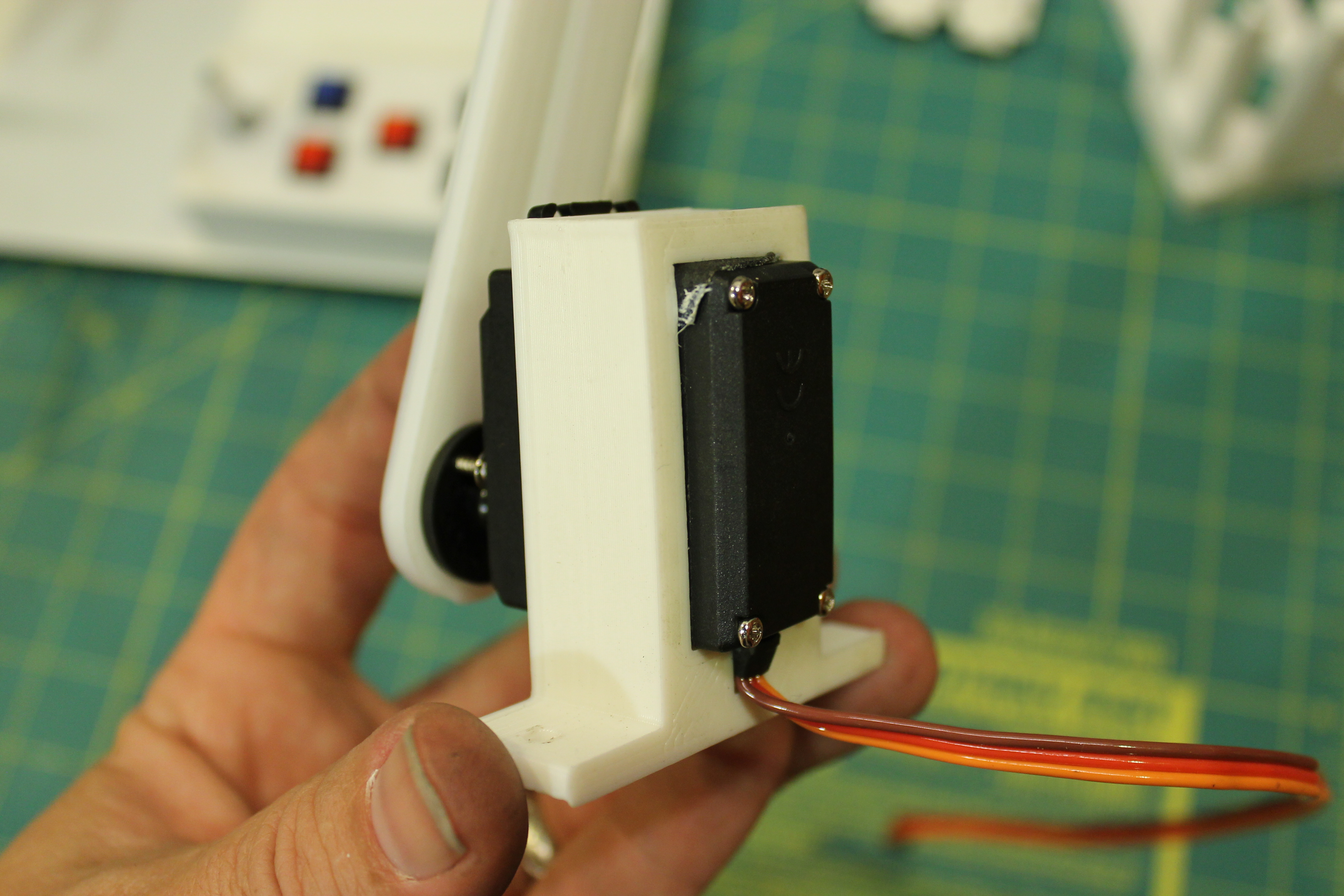
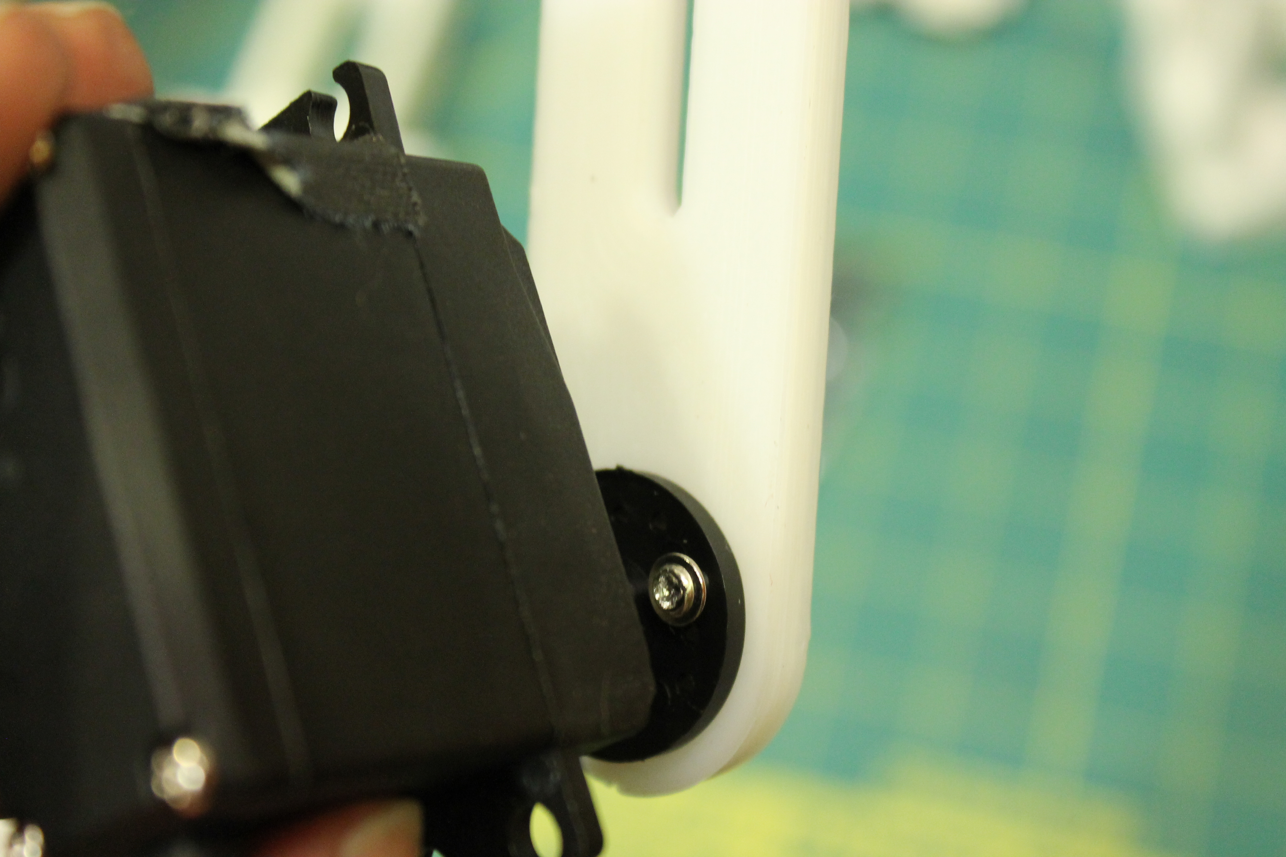
Slide the servo in to the servo mount.  If the fit is a little loose, you can wrap some tape around the servo to make it more snug.  Use m3x16 screws to mount the servo in to the slots next to the control box.  Plug the servo in where it says Servo on the left edge of the control board, with the brown wire at the bottom.

IMG_5670

The filament intake can be mounted vertically or horizontally.  Mount it vertically if the base of the wider will be mounted to the wall, or otherwise positioned vertically.

IMG_5671

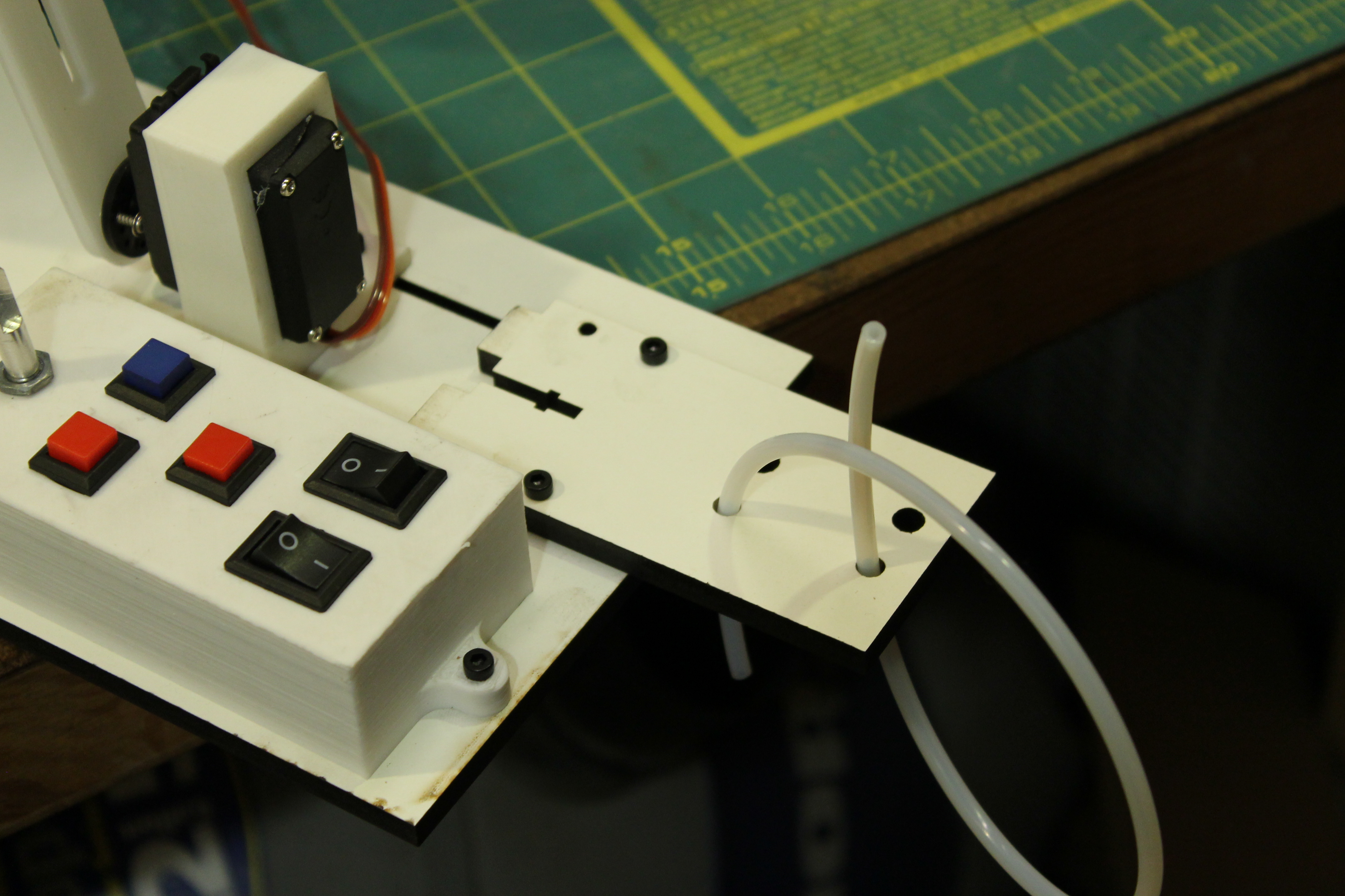
Use M3x16 screws to mount the board horizontally if the winder will lay flat, as on a shelf.  Loop 12″ of 4mm OD PTFE tube into the smaller, bottom hole from below, and back through the upper hole from below as well.  The filament will pass through the tube and create enough drag to provide adequate tension to the spool.  The larger pair of holes is for 6mm OD PTFE tube to accommodate 3mm filament.

IMG_5673

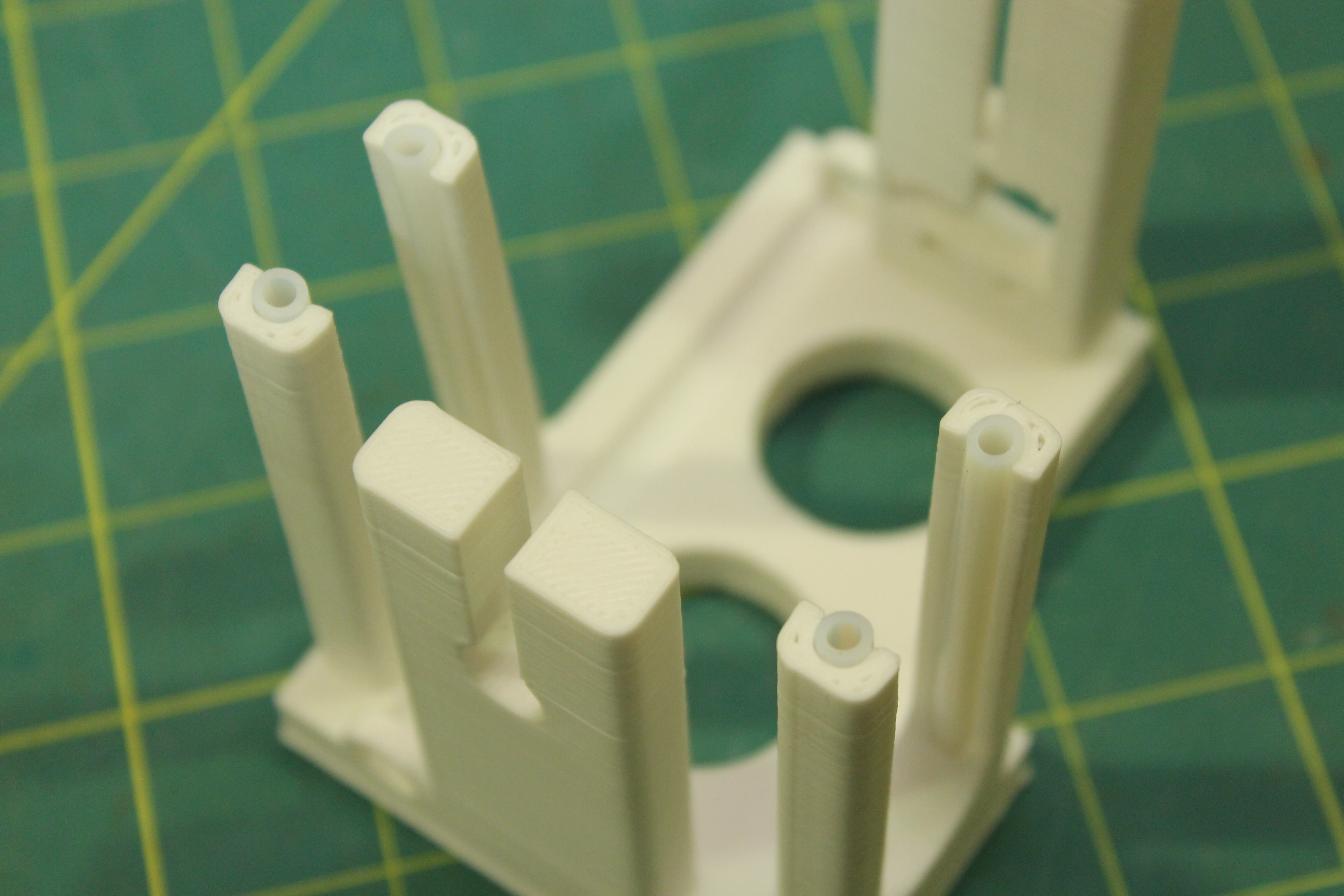
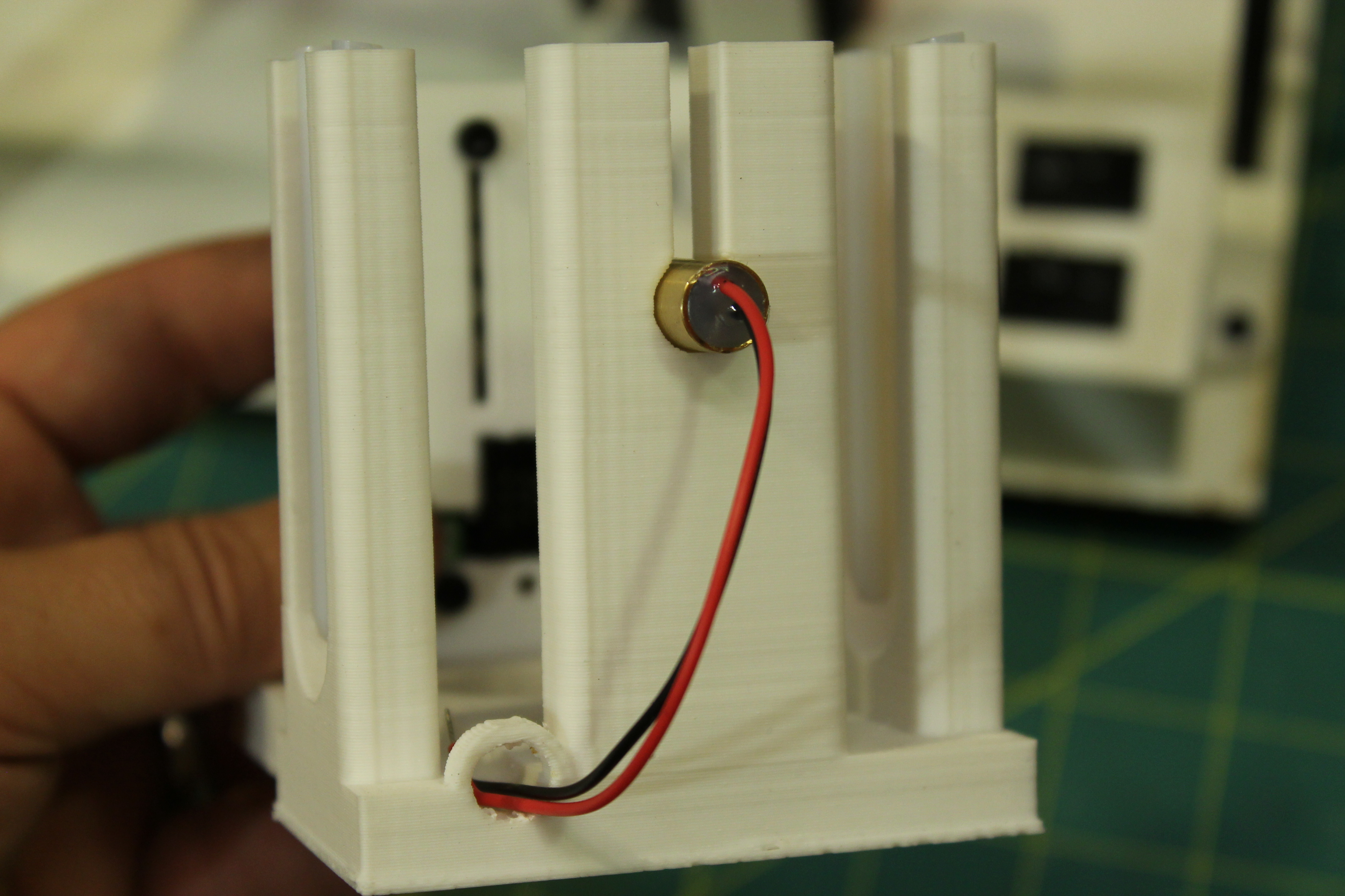
Slide the short sections of tubing into the channels in the filament guides on the laser mount.  Take care not to break the guides.  Put the laser into the laser mount, and run the wires through the channel in the base.  Using a tiny screwdriver, secure the wires in the terminal block on the sensor board, with the red wire on top.

IMG_5674 IMG_5675

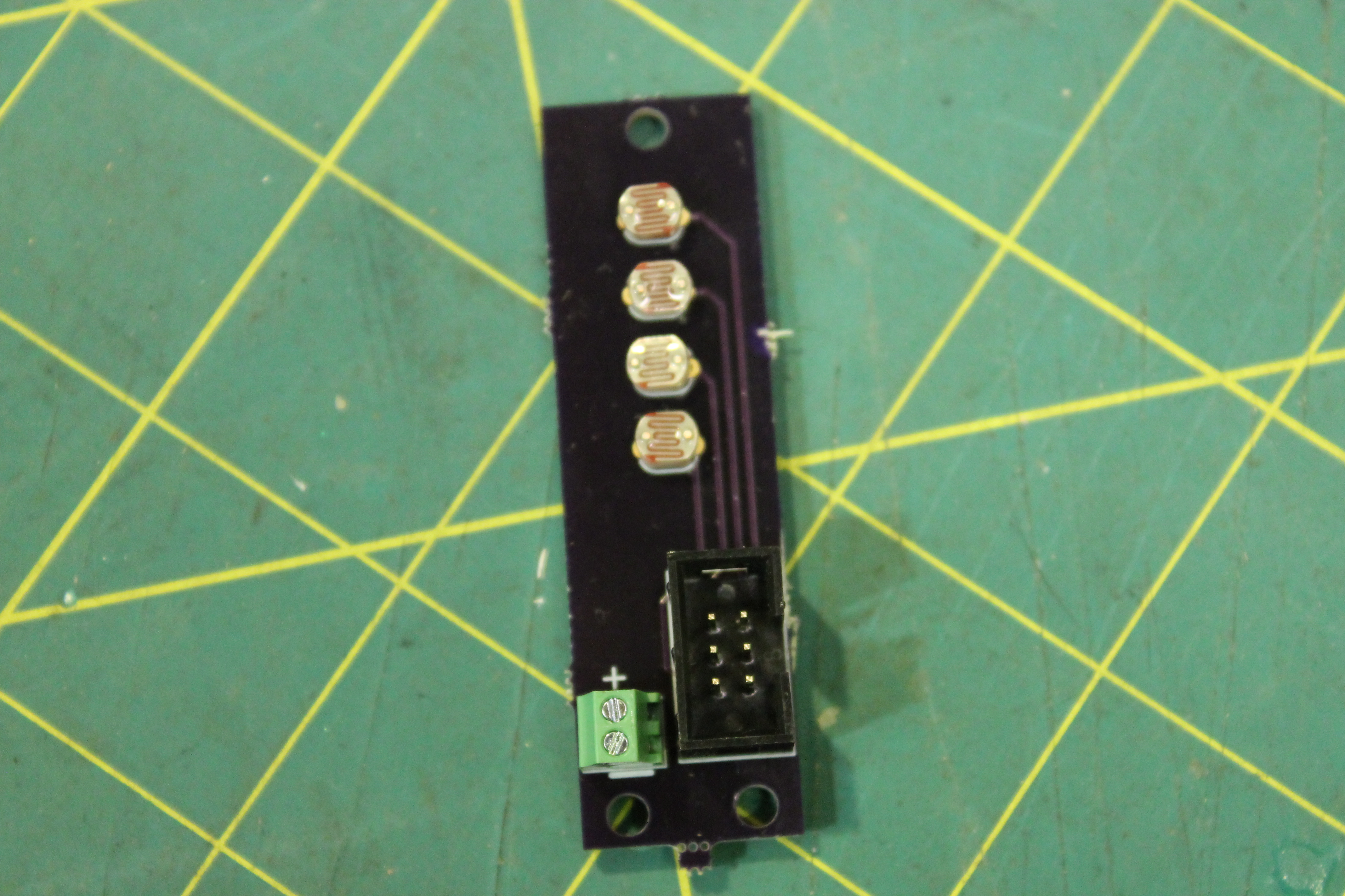
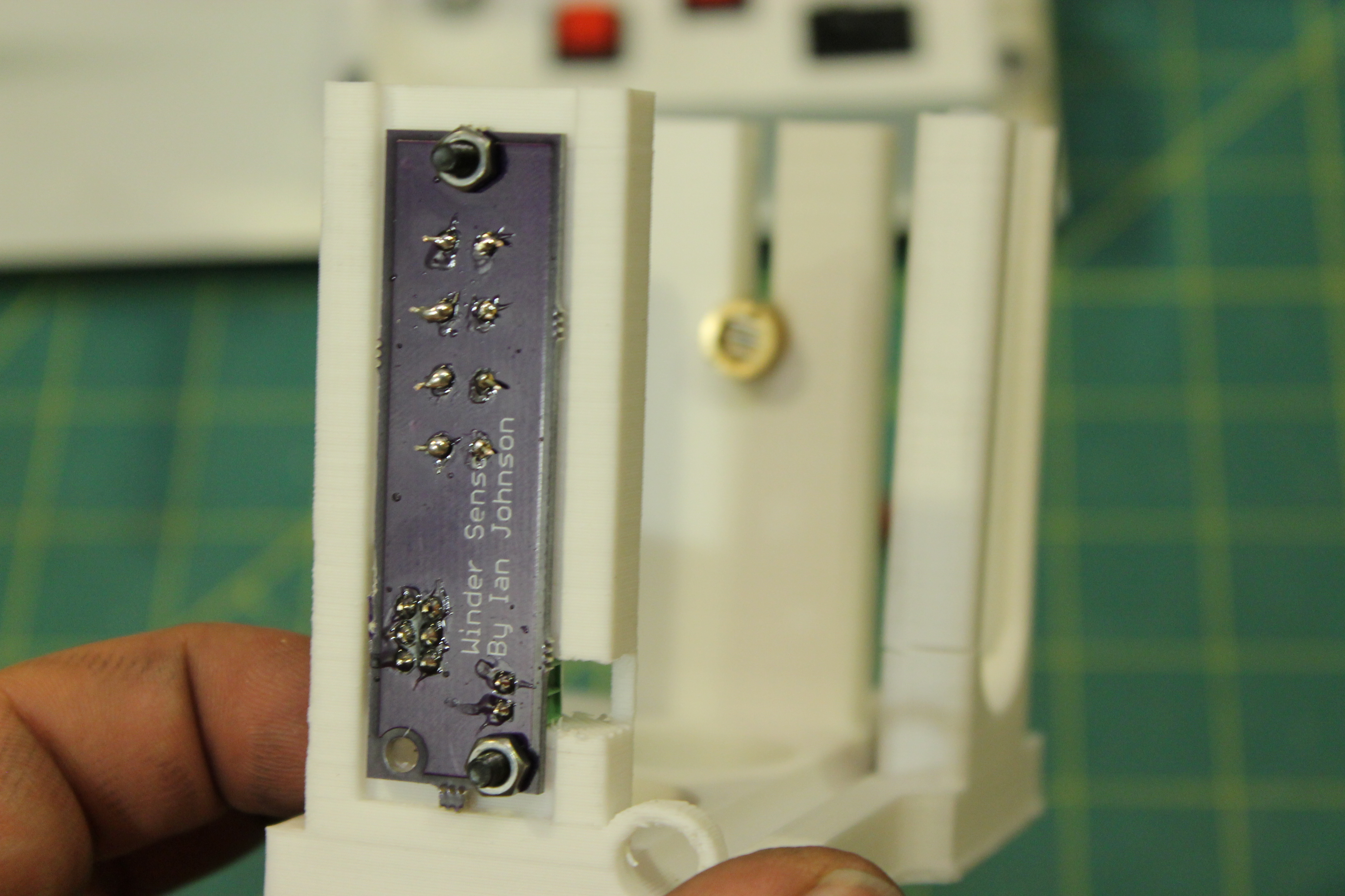
Using 2 M3x16 screws, mount the sensor board with the photocells facing the slot.

IMG_5676

IMG_5678

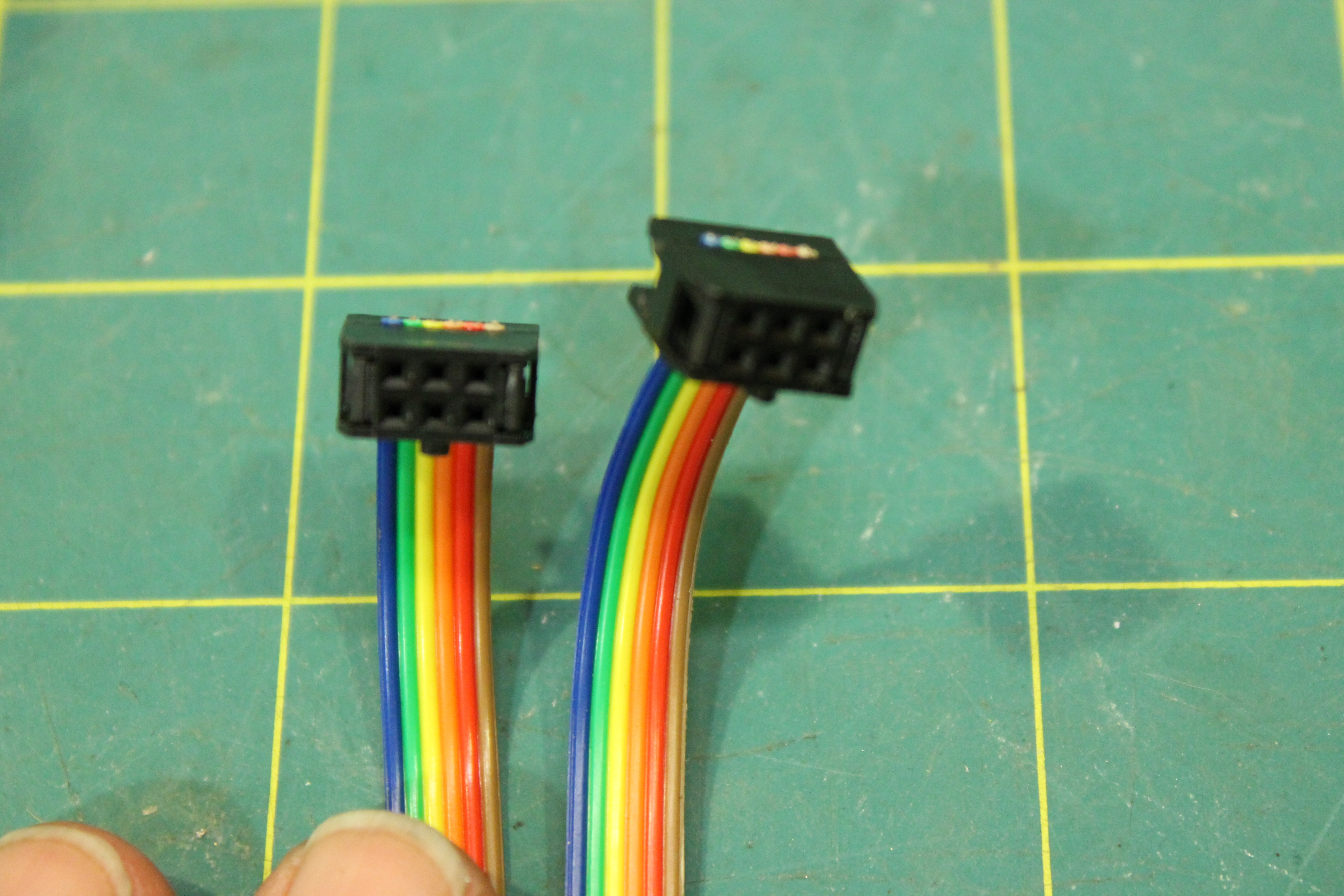
Add crimps to the ribbon cable.  Slide the cable into the crimp from the side that has the notch.  Orient the cable the same way for both crimps.  Squeeze the crimp closed using a vice to apply even pressure, then trim away any excess wire.

IMG_5679

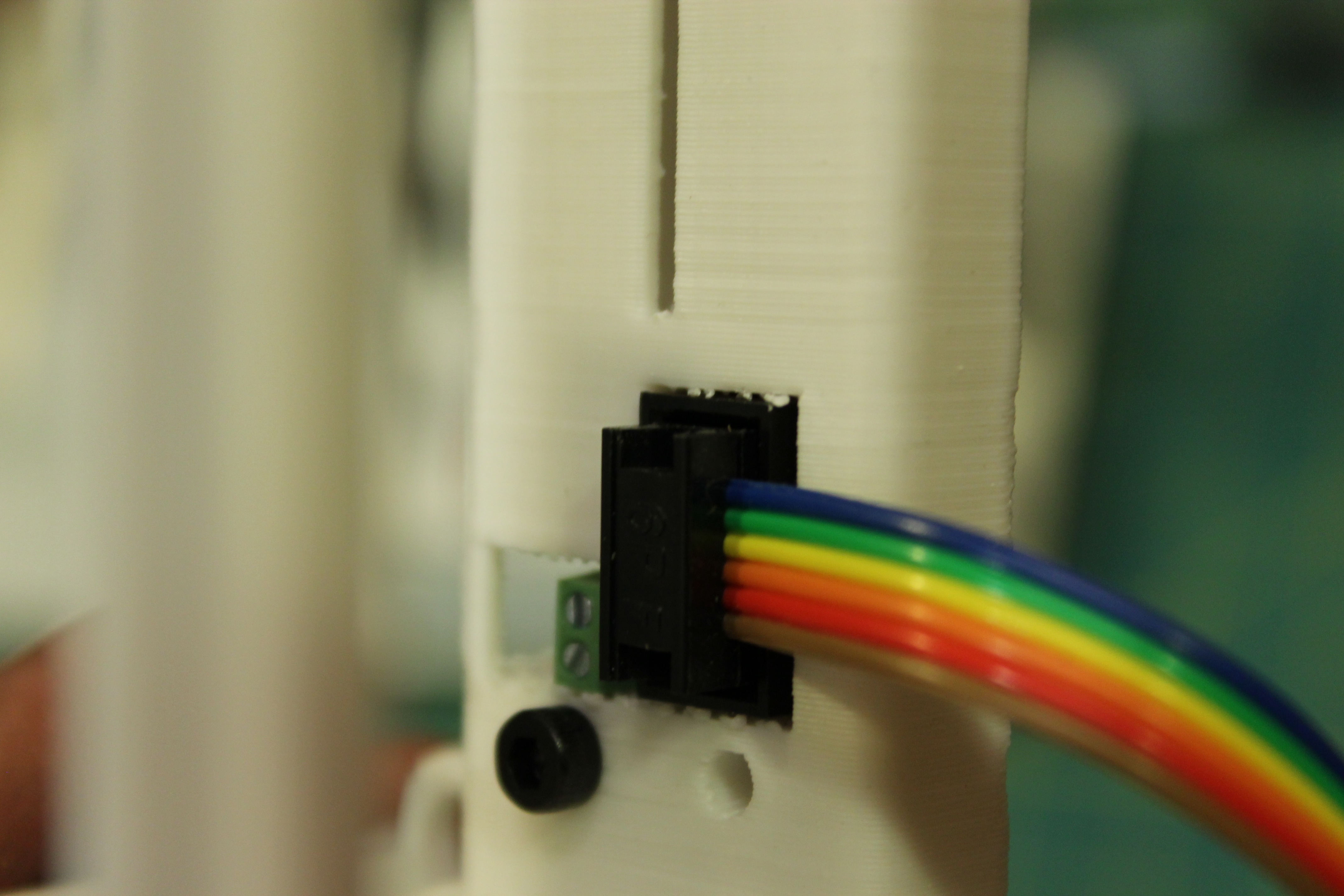
Plug one end into the sensor board, and the other end into the control board.IMG_5681

IMG_5680

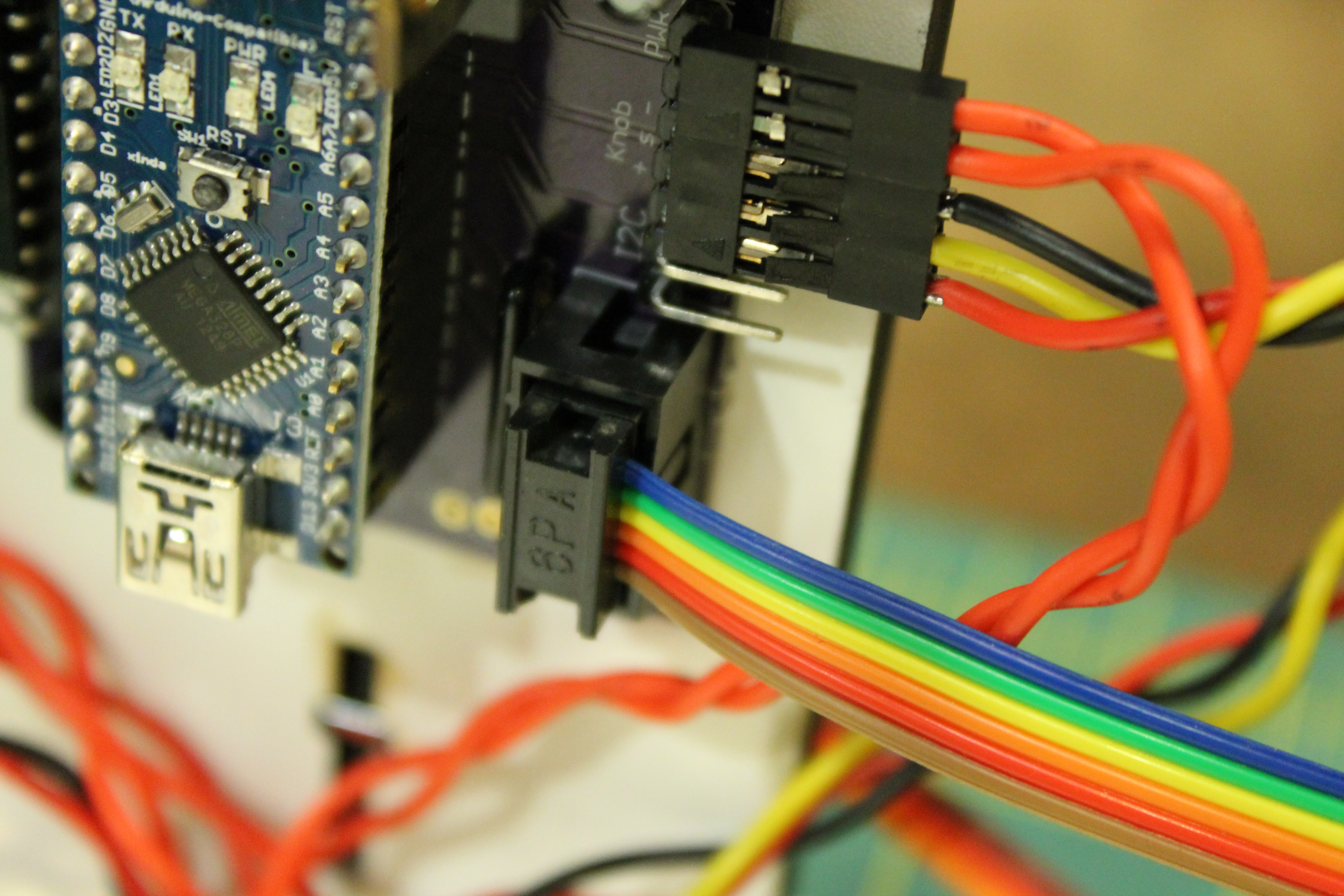
Turn on the right switch for power.  The left switch changes between Manual mode, where the speed of the spool is controlled by the knob. and Auto mode, where the speed is controlled by the sensor.  Press and hold the left button and turn the knob to position the guide arm at the left limit, to set the furthest point the guide will travel in that direction.  Press and hold the right button and turn the knob to position the guide arm at the right limit .  When in Auto mode, holding the middle button will allow the knob to change the current position of the guide.  The direction the guide traveled to reach that position will be the direction it continues to move as the spool turns.

When in Manual mode, the middle button calibrates the sensors.  When the button is pushed, the winder will go into calibration mode for 5 seconds.  During this time pass a piece of filament back and forth between the filament guides to cast a shadow over all of the sensors.  The winder will record the darkest and lightest values during those 5 seconds and determine what is shadow and what is ambient light.

After calibration, you can test the sensor by waving a piece of filament over it while in Auto mode.  The motor should speed up when the filament drops below the middle sensors, and slow down as the filament rises.

Jammed J-head

I was starting to get intermittent extrusion with my J-Head.  It wasn’t completely jammed, but I could see the idler bearing stop turning every now and then while the gear was still rotating.  If the bearing isn’t turning, the filament isn’t feeding.  It was obvious in the print of course, with missing lines in the solid fill and weak walls.

I ran a violin string into the nozzle to try and break up whatever was getting in the way and it seemed to work for one or two prints, but then go back to getting jammed.  I thought it was a little odd because I was using a .5mm nozzle which should be a lot less likely to clog.  I took off the nozzle and put on a .35 nozzle that I knew was fine, expecting to go back to printing as normal, but it still jammed.  That meant the problem wasn’t the nozzle, but something with the PEEK.

Clogged nozzles are common enough, but it isn’t always the nozzle opening that is the problem when it comes to a hot end that won’t extrude.  The jam can be happening higher up.  The J-Head and similar hot ends have a PEEK barrel with a teflon tube inside.  There are threads at the bottom that hold a brass barrel which butts up against the the teflon, and on the J-Head there is a hollow set screw at at the other end which keeps the teflon from sliding out the top.

It is very important that the brass barrel stay pressed firmly against the teflon liner.  The filament will start softening and melting at the junction between the two.  If there is any gap, it will fill with melted plastic and some of the force needed to push plastic out of the nozzle will instead push it sideways into the gap and attempt to force the barrel down.

After I pulled the filament out of the hot end and took off the nozzle/barrel I found this bit of plastic left behind at the bottom of the teflon liner:

IMG_4885The cone shape at the top is from the filament stretching as I pulled it out, and the plug at the bottom is a small amount that was in the barrel.  The disc is the plastic that filled the gap between the barrel and the teflon.

I don’t know what caused the gap to form in the first place, maybe the teflon managed to compress a little bit.  Just putting another nozzle on didn’t work because the bottom of the teflon maybe had moved up a little bit, or maybe I didn’t get it screwed on as tight as the previous barrel.  When I put the hot end back together, I first took out the set screw at the top and pushed the liner down a little with the back of a drill bit.  Then I screwed on the barrel which pushed the liner back up a little, insuring that they were in contact with each other.  Then I put the set screw back in and tightened it down so it would keep the teflon pressed against the barrel.

20130818_151151

Hollow set screw at the top of the J-Head

On the 1.75mm J-Heads there is a short piece of PTFE tubing in the set screw to guide the filament through the set screw into the liner.  You have to get it out before you can remove or tighten the set screw.  I did it by sticking a sharp point into the inner wall and levering it out.  Be careful when doing this because it might suddenly fly across the room never to be seen again.

There is an all-metal E3D hot end waiting at the post office, so hopefully this is the last time I will have a problem like this.

Winder – Starting the Loop

Filament is very finicky and a bit difficult to manage.  The way it is looping down from the extruder and back up to the winder looks like a drooping length of string, but it doesn’t act that way.  It is flexible for the first couple of inches while it is hot, and then sets into a shape which may be a straight length or a bend, depending on what it was doing when it cooled.  Then it runs along a path like string, but being semi-rigid it also supports itself along the way.

For the filament to feed consistently, it needs to maintain the same shape as much as possible by keeping the same orientation as it hardens.  If the shape of the bend changes near the extruder, then that bend will push the filament around when it gets to the puller, creating another change in the bend at the extruder which pushes the filament when it in turn reaches the puller in a never ending cycle.  You can see it in action in this timelapse-

The key here is that the filament pushed back behind the nozzle opening, creating a tighter bend in one spot.  When that bend got near the puller it pushed the filament behind the nozzle again.  No amount of tweaking on the speed could compensate for that.  It only ran about an hour, and then developed a kink that was not going to make it through the puller, so I stopped it.

I also took the fan off halfway through.  With the fan, any extra movement of the filament near the nozzle gets quickly hardened into a permanent bend.  If it stays soft longer, there is a chance for it to straighten out again before hardening.  Cooling would be beneficial if it could freeze the filament right as it exits the nozzle, before it has a chance to move around much,.

Here is another attempt at the loop, but this time I moved the extruder or winder back and forth to make sure the filament kept the same angle coming out of the nozzle no matter how it was pushed around.  Eventually the inconsistencies created while guiding it to the puller worked themselves out and it ran steadily for 3 hours until it was time to stop it for the night.

Filament Winder – Puller

IMG_4519

The puller controls the speed of the filament coming into the winder, and isolates the tension created by the spool from the extruder.  It’s run by a 37mm 15 rpm gearmotor, mounted by 2 M3x12mm screws.

Print the puller mount, and drill the holes so that they are the correct final dimensions.  Use a 3mm bit for the two holes at the top edge, and the holes for the motor, which are a little above center.  On the back drill the top two holes a short way in with a 6mm bit and push some M3 nuts in.

IMG_4522Mount the motor with M3 screws so that the edge of the motor sticks up above the mount, to allow room underneath for the bolt that holds the mount to the board.

IMG_4521

Print the two extruder pieces, and clean out the support and trim any wayward threads from the bearing holder.  The 625 bearing should snap in and spin freely.  Use a short M5 bolt to hold it in place, but don’t use a nut.  Take care that the bolt does not extend from the back, or it will cause the holder to twist away from the mount.

IMG_4520Screw the base part of the extruder on to the mount with a M3 18mm bolt.  Ideally the head of the bolt will hold the part snug against mount without sticking out the back where it will get in the way of the motor.  Use some washers on the front if the bolt is too long.  Attach the bearing holder with a bolt long enough to go through both pieces and the mount.  Cut a section of spring about 10mm and wrangle it into the recess on the base part of the extruder.  Tweezers might help here.

IMG_4524Print the two halves of the tension wheel and glue them together.  Push a 608 bearing in through one side as far as it goes.  Put a M8 bolt through the larger hole of the tension arm, add a nut, and slide the wheel up against the nut.  Tighten another nut against the other side of the bearing in the wheel.

The potentiometer has a little tab that sticks out to keep it from spinning in its mount.  You will need to drill a small hole in the mount next to the hole for the shaft to accomodate this little tab.  Put the shaft a little ways through the first hole and slide on the nut that came with the potentiometer before pushing it the rest of the way through the second hole.  Use some tweezers or skinny pliers to screw the nut onto the threads on the potentiometer shaft.  It’s tricky, but you should be able to get it in a minute or so.

Turn the pot back and forth until you have it near the middle of its range of motion, and press the arm onto it.  Position the mount alongside the wide part of the motor with the wheel lined up with the upper filament guide hole and screw it down to the board.

IMG_4518Use some tiny screws to attach a spring that is 1.5″-2″ long to the arm and the side of the mount.  It should take only a little bit of force to hold the arm upright against the pull of the spring.


Filament Winder – Spool Mount

Spool Front

The spool mount is made to be easy to take spools off when done and replace them quickly.  The spool itself has printed ends which fit into a 6″ length of 2″ Shcedule 40 PVC pipe. It’s easy to make as many as you need at home, and they are made to fit smoothly onto a 3/4″ PVC pipe.

Spool EndStart by cutting two pieces of 1/2″ MDF to 16″x8″ and glue/screw them together at right angles.  Drill an 8mm hole about 7″ from the base, and 1″ in from the left side for the threaded rod..  Use a spade bit to drill another hole 3/4″ wide about 1″ down from the top and 2.5″ in from the left edge for the motor arm.  Cut a section of threaded rod about 9″-12″ and put it through the hole with a nut and washer on each side of the board.  Slide the spool stop against the nut on the front of the board.

The spool stop looks like a cylinder with a hole in it, but it is actually shaped like a small spool.  There is a single thread wall (.42mm wide) around the edge to act as support, which should be cut away.  This will be used later on along with a screw to keep the mount from sliding off when you remove a spool.

The Class 200 3/4 PVC pipe has an ID that is slightly larger than a 608 bearing.  If you wrap about 2-3 layers of electrical tape around the outside of the bearings it will make a snug fit.  Place two bearings on the rod far enough to provide good support for the spool, with a printed washer and nut on each side of each bearing.  The nut of the inner bearing should also hold the spool stop in place.  The washers will let you tighten the nuts against the bearings without restricting their motion.   You can save time threading the nuts on by using a drill to spin the rod.

IMG_4500 IMG_4502 IMG_4501

The mount for the hall effect sensors is also pictured, but that will be added in later when the electronics are done.

Cut a section of pipe long enough to reach the end of the spool and slide it on over the bearings, up to the end of the spool stop.  Slide the spool gear onto the pipe with the flange pointed toward the back board, flush with the end of the pipe.  With a 3mm bit, drill through hole in the flange, through the pipe.  Put a M3 16mm screw through the hole.  This screw will bump against the insides of the spool stop and keep the pipe from sliding off when you remove a spool.

IMG_4503 IMG_4504There are four small holes in the gear.  Drill them out to 4mm and put 3 M4 18mm bolts through them, with nuts on the other side.  The bolts will slide into matching holes on the spool to lock it in place, and the nuts keep the spool back far enough that it doesn’t drag against the motor gear.

IMG_4506IMG_4508

IMG_4510

Print Lyman’s gear motor arm and washer and mount them in the 3/4″ hole.  Use M3 screws to attach the gear motor and slip the small spool gear onto the motor shaft.  If it is too tight, drill it out with a 6mm bit.  If the motor arm was a tight fit into the hole, you are done with this part.  If it is a little loose, you will need to hook a small spring to it, with the other end screwed into the back board.  If the gears are not held tightly together, the motor will be pushed away whenever the filament gets a little hard to pull.    If you want the spool to spin freely, simply lift the motor up.

There’s more to come, as I can get it written.


Filament Winder – Intro

IMG_6149

I’ve been working a few months with the beta of the Filastruder, which will start shipping kits soon from it’s Kickstarter campaign.  I was never very happy with letting the filament extrude onto my (often dirty) garage floor, so I have been working on a winder for the filament.  It has been tricky because filament doesn’t act like string, it is stiff and tries to maintain a shape that may be curved or straight.  There are a few other challenges that need to be addressed by a winder-

A winder needs to sync with the speed of the extruder, which is a bit variable.    If it is a little too fast or a little too slow, over several hours it will outrun the extruder, or let the filament pile up and get backed against the extruder making what looks like plastic ramen noodles.  Also there needs to be some tension on the feed to the spool to force the plastic to coil against it.  The amount of tension depends on how fast the spool is turning, but the speed it has to turn to maintain a given amount of tension will change as it fills up.  Lastly the filament needs to be guided back and forth across the spool so it lays down evenly rather than bunching up in the middle.

Originally I tried pulling the plastic directly from the extruder like the industrial machines do, stretching the filament down to the desired diameter which is determined by the speed of the pull.  I wasn’t able to get close enough tolerances doing this because the speed of extrusion isn’t constant.  When the filament can drop freely, variations in pressure inside the extruder cause the filament to come out faster or slower without really affecting the diameter.  When filament is being pulled out at a fixed speed, variations in extrusion will change the diameter instead.

What I have done is let the filament drop into a loop and then get pulled up again into the winder.  This way any pulling by the winder will act on the loop and not the filament at the nozzle.  There are two photo sensors at the bottom of the loop with a line laser shining on them.  When the winder pulls too fast, the loop will rise and shade the upper sensor which slows down the motor.  When the loop drops low enough to shade the bottom sensor the motor speeds up again.  The bottom of the loop then slowly rises and falls within about .25″ which maintains a steady enough pull on the plastic coming out of the extruder.

The winder has a puller which syncs the takeup with the extrusion and isolates any other handling of the filament from the extruder.   There is a mechanism to regulate the tension on the spool, and a guide arm waved back and forth by a servo.  The whole thing is powered by an Arduino Uno.

It is still a work in progress, but close to being finished.  I wanted to start documenting it so others can begin to play along, and maybe begin getting parts together.  There a lot of printed parts, which you can find at Thingiverse.  I don’t have a detailed BOM down to the size and number of screws, but I will list enough to get going.  I haven’t decided if I will set up sales of a kit somehow, but at the very least I would like to get custom PCB’s made.  This is set up on a breadboard at the moment which works, but is a bit clunky.  There will be a mix of metric and imperial which I apologize for.  I like to use metric whenever possible, but some things in the US are imperial only.

In addition to printed parts you will need-

  • 2 pieces of MDF 8″x16″
  • 2 37mm gear motors 15 rpm.  Ebay, probably from China.  Order now and start printing while you wait for the boat to come in.  These are for the spooler and puller.
  • HiTech standard servo – Amazon or the local RC hobby store for the filament guide.
  • 625zz bearing for the puller idler
  • 3 608 bearings for the spool mount and tension roller.  Get a pack of 10, it’s always good to have extras around.  I’m working on a spring loaded caliper to measure the filament which will use 2 more of them.
  • A short spring for the puller idler
  • 1/2″ OD latex tubing from http://www.latex-tubing.com for the motor shaft on the puller. Some easier to get rubber tubing may work, but latex is soft and has a good grip
  • M8 threaded rod for the spool mount
  • 3/4″ Class 200 PVC pipe for the spool mount (thinner than schedule 40)
  • 2″ schedule 40 PVC pipe for the printable spool
  • Arduino Uno rev3
  • Half size breadboard
  • 12v power supply.  I found a pile of them at the thrift store.
  • Solid wire for breadboard jumpers
  • Stranded wire for hooking up hardware
  • 2 photo resistors
  • 4 10k resistors
  • 2 MOSFETs for the motors
  • 2 1N4001 diodes for the motors
  • Some Molex single row wire housings like these – a handful of 2, 3, and 4 wire versions.
  • Crimps to go with the housings like these from Mouser
  • Straight PCB headers, 30 or so
  • A small spring, about 1.5″-2″.  The kind with loops on the ends, meant to stretch.
  • Various M8 nuts and washers
  • Short wood screws
  • M3 nuts and bolts ranging from 12mm-20mm
  • 2 10k potentiometers, 16mm diameter with a long shaft
  • 2 hall sensors for detecting spool rotations.  Mouser has them for less than $1
  • Cylindrical neodymium magnets, 1/4″ to go with the hall sensors.  Amazon has a pack of 20 for $10.  You only need 2, but they are useful to have around.
  • A coupe of microswitches with levers, similar to endstops on a printer.  Adafruit has some, you can probably track down an equivalent at Mouser.

IMG_6150

Next I will start with the spool mount.

Slicer Shootout Pt. 4

One of the other models that Make Magazine used in their 3D Printer reviews was Cushwa’s Owl from Thingiverse.  I thought it would be a good test for the slicer comparison as well, something more sculptural than geometrical.  This was printed straight from Thingiverse without any cleaning or modification other than scaling it down 60% to save time.  I have two KISSlicer prints because I accidentally ran one scaled at 50%.  Since I still had hairspray and kapton on the bed from trying to prevent warping in the Torture prints, the Owls were stuck pretty hard.  I broke the Cura print just above the talons trying to get it off, so that isn’t a printing artifact down there.

The Owl has some challenging texture in its feathers.  The tips are largely unsupported, which gets complicated in the lower half of the body since the perimeters have a bit of overhang due to the body widening from the talons up to the middle of the chest.  An additional challenge is the unsupported underside of the beak which needs support to print properly.  It’s another chance to see how the slicers deal with a bad situation.  The back of the owl is a smooth, even curve which provides a good contrast to the texture in front, and the top of the head is a shallow dome, which can be challenging.

OwlsBetween the Slic3rs, 072b seemed to do the best at overhangs, with few loops at the feather tips and under the beak.  However the surface of the feathers is cleaner in 097, especially in the upper chest.  The upper chest is also very good in Cura, but it suffered a lot in the inward slope toward the talons.  Not a lot of dropped loops, but it’s possible that the perimeters aren’t laid out with enough overlap between layers to maintain a consistent alignment.  KISSlicer has the smoothest surface on the feathers and maintains it the best in the underside of the body.  There are a few misaligned layers however.

Owl FacesKISSlicer also handled the underside of the beak best, but had some odd lines across the face.  They are happening at the same spot in both prints, so it isn’t some random wiggle from the printer, unless there is something about those layers that is difficult for the printer to execute properly.  Those misaligned layers are very similar to the ones above and below, so there shouldn’t be anything unusual about those spots. Cura is inconsistent there as well, with Slic3r handling it the best.

Owl_2 SplitSlic3r 097 is the clear winner at the back of the owl with no blobbing or misalignment.  Slic3r 072b has the blobbing from perimeter ends, and KISSlicer has a visible seam as well, though it was mostly flush to the surface.  It also had a few odd perimeters that were shifted in X, recessed on one side and sticking out the other.  It looks like layer shift, except the rest of the layers are in the right place.  It also happens in the same places for both prints.  Cura failed here with a bunch of bad layers.  It is possible that there was an issue with the Z axis of the printer because it looks a little like squished layers.  If so, it was intermittent enough to not show in the other prints.

Owl 3 SplitCura looks like it overextruded a little bit at the top of the head, yet still left some gaps, and the tufts are a bit rough.  Slic3r 072b has perimeter starts in the middle of the tufts, which 097 hid better.  The perimeters are a little uneven in 072b which 097 improves on, but still left some gaps.  KISSlicer has the most steady lines and solid fill.

It’s a close call between Slic3r 097 and KISSlicer for the owl, only because of the way KISSlicer handled the back.  There is a new version coming out soon however, and I’ll have to see if it shows any improvement in this model.

Torture Test Quality Check

I’ve been wondering why the columns on the Torture Test printed so badly for all of the slicers when I’ve seen them all do better than that before.  I tried a single column with Slic3r 096 which was one of the worst for that section.  I also wondered if there might be a problem due to the model coming from Tinkercad, so I printed one column from Tinkercad, and another from Alibre-

Tinker vs AlibreThey both look pretty good, aside from where I gouged them with my scraper.  My concern with Tinkercad was that STLs generated there are typically fairly low resolution.  You can make out the increased faceting in the print but it didn’t cause a problem otherwise.  I thought there might be a difference due to the bad columns being part of a larger print.  I cut out the rest of the model and tried a print of only the column section.

Cura ColumnsIt’s a little better.  The misaligned layers seem to be gone, leaving only blobbing and artifacts related to the start and end points of the external perimeters. I had used Tinkercad’s STL import feature to convert the original torture STL to solid, and easily add other elements.  There is some decimation that happens in the process and who knows what else, so I decided to compare meshes.  This is the original-

Mesh OriginalThose columns are pretty high res, but completely uniform.  Here is the mesh from Tinkercad-

Mesh TinkercadThis is a lot more jumbled, with the surface resolution of the columns changing from bottom to top.  Compare this to the Slic3r 096 print-

4_096SDThe columns start out smooth at the bottom, and become more blobby where the resolution increases.  The column with the chamfer shows the pattern as well.  In the mesh, the column starts out simple, becomes more complex rising toward the chamfer, then becomes consistent and well ordered after the chamfer.  The effect of that change is clearly visible in the print.

I decided to print the original, unaltered Torture Test in Cura and see how much difference the mesh made in the final print.

Compare 3Compare 4

There is a small improvement, but it isn’t drastic; a few less lines in the columns and a smoother surface on the arch.

Here is a simpler set of columns drawn in Alibre:

Mesh ColumnsAnd here is the print in Slic3r 097:

Columns_1_097It seems as if the columns were all rendered with the same number of faces, but on the smaller columns those faces must be much shorter.  It seems that with Slic3r, it begins to have more and more trouble as the mesh gets denser.  Here is a KISSlicer print of the same STL:

Columns KS_1KISSlicer seems to have a little trouble as well, but unlike Slic3r, it only shows in the smallest columns.  It seems like the slicers have a minimum length of segment that works well.

I also wanted to test perimeter speeds.  You can get a much better surface quality by keeping the speed of the outer perimeters low, while letting the inside of the model run faster.  I printed the column set in Skeinforge once at 50mm/s like all the other prints, and once with the perimeters at .25mm/s.

Skeinforge 39 ColumnsThe poor quality only begins in the thinnest column as it was with KISSlicer.  The slower speed noticeably improved the surface of the last columns, but didn’t eliminate the errors completely.

This really was a torture test, not just in the features, but also the inconsistent mesh.  This exercise wasn’t about finding the best settings and creating the nicest print, but seeing how the slicers perform relative to each other.  The torture model happened to test how well each of the slicers dealt with a mesh that was  disorganized, and I think KISSlicer handled it with the most grace.

In the next post I will try some owls for a more organic print.

Slicer Torture Test

One variable I was concerned about in making the test prints was the USB connection.  Sometimes the flow of instructions can get interrupted, causing the printer to pause and wait, leaving a blob in the process.  If a little too much CPU gets tied up for a moment, it can create one of these pauses.  To prevent this, I ran the test prints from an SD card mounted on the printer itself..  I did a comparison between USB and SD with Slic3r 096, and there is a slight, but noticeable improvement in the SD print-

USB vs SD

Overall it looks pretty horrible, at least in the columns.  On to the overall results.  At the end I will have a link to download all of these at high resolution since the viewer on the blog doesn’t let you really get into the detail.  Warping at the corners was always a problem.  These were printed on Kapton with hairspray in a closed case.  On some I used a heater to get the ambient up to 60C which helped keep the corners down, but never completely eliminated the warping.  Even though the corners lifted the prints were very hard to remove even at room temperature.

Torture_1I’m surprised to see stringing across the holes in the Cura print, even though the retraction settings were the same for all.  The sides of the cube with Cura and SF39 split in a few places because the narrow walls were left hollow and weak.  Slic3r had a consistent problem with the end of the arch coming loose.  The echo pattern to the left of the holes is supposedly due to the outer perimeter speed being too fast.  Ideally you would set that to a low speed, and run inner loops and infill faster to save time, but not all of the slicers had that ability.  The Slic3r 096 print doesn’t have the holes because I had already run that one before I thought to add them.

Torture 2Kisslicer wins for best arch.  Slic3r might have been better, but it is hard to tell since it knocked it over every time.  Kisslicer and Slic3r also had more consistency in the flat walls.  The columns were a challenge to all slicers, and I don’t know why they all came out so poorly.  You might think it would be mechanical issues with the printer, however they sucked in different ways, and did it in a consistent manner. I did some more testing related to that, which I will get into later.

Kisslicer handled the columns best, with some slight gapping at the point where the outer perimeter turns inward to the fill.  In Slic3r I left Randomize Starting Points unchecked.  That setting is supposed to prevent a seam running up the side of cylinders from the perimeter starting at the same point in every layer.  However it usually causes blobs to be spread all over the surface.  I suspect Slic3r 096 was randomizing anyway, while 097 respected that setting.

Torture 3Cura and SF39 had a lot of variations in the flat wall, and especially the column perimeters.  Kisslicer and Slic3r 097 had the best walls and a little variance in the column perimeters, while 096 had a lot of random blobbing. 072b is OK, somewhere between 096 and 097 with a little more pronounced seams.  In the 097 print you can see a little blobbing on the face of the cube toward the bottom. This is from moves between the column and wall, so retraction is a little less effective there than the Kisslicer print.Torture 4

Kisslicer, Slic3r 097 and 072b are doing the best on the texture wall.  072b managed to avoid dropped loops and maintain layer alignment all the way through.  Kisslicer and 097 also didn’t drop threads, but had some layers with a little setback.

Torture 5Cura had the best solid top layers, watertight and consistent.  096 was decent, 072b borderline, and 097 and Kisslicer were far too loose.  This could be fixed in 097 by reducing the nozzle diameter so the threads get placed closer together.  I’m not sure how to fix that in Kisslicer.  Increasing the flow rate will close up the gaps, but it will also make the perimeters wider, making the outer and inner dimensions incorrect.

Cura and SF39 left the narrow walls of the cube unfilled, which weakened them so much that some of the layers split apart at the corners.  096 filled the thin wall with a zig zag fill, executing it better than 096.  Kisslicer and 072b seem so have used straight lines to fill the wall which I prefer since it looks a little neater.

096 didn’t handle filling the thin wall of the hollow column at the upper left very well.  072b did a little better but mangled the inner perimeter.  Kisslicer’s is decent with some concentric fill, but Cura has the best one, as well as the smoothest surface of the arch.  The corners of the arch show quite a bit of overshoot, demonstrating that 50mm/s is too fast for the Solidoodle to be running outer perimeters.
Torture 6Slic3r 097 and 072b predictably had the best bridging performance.  Slic3r has the ability to run the fan for bridges, though 096 seems to have ignored that setting.  Cura and Skeinforge can only speed up and lower the flow to stretch the filament over open space (which Slic3r was also set to do) and was moderately successful.  Kisslicer doesn’t have any bridging settings at all.

Torture 7The chamfer under the large cylinder was a challenge that none of the slicers was able to handle, though 096 came close.  If the placement of the thread is a little too far to the inside, it won’t stick and get pulled into a straight line instead.  I’ve printed this kind of feature without trouble at 60-70mm, but at 20mm or so the curve is too tight.  A slower speed might have helped, to provide as much time as possible for the extruded plastic to bond to the lower layer.  Even though it didn’t do very well on the chamfer, Kisslicer handled the overhanging perimeters on the underside of the arch better than the others.

The overhanging corner is something that no printer will accomplish neatly without support, but Slic3r 097 managed with the fewest dropped loops, most likely due to the fan.

I was surprised at how badly the columns came out overall, which would seem to point to a problem with the printer.  However the errors were different for each type of slicer, and consistent between versions.  Also they happened the same when the same print was run twice as in the SD/USB comparison.  These prints were scaled up 150% from the original model so it wouldn’t be too torturous, but I did also print them at the original, smaller size.

Mini Torture 2Mini Torture 4 Skeinforge 39 still mangled the columns, Kisslicer had small gaps up the seams, 096 was blobby, and 097 had misaligned layers.  All of the Slic3rs still knocked over their arches.  I did a few tests to try and figure this out, which I will cover in the next post.

Later I will have tests with Cushwa’s Owl from Thingiverse for something a little more organic, as well as tiny Yodas at .1mm layers.

Slicer Comparison

Probably the most important step in 3D printing is the slicing- the conversion of a 3D mesh into a set of toolpaths for the extruder in the form of gcode.  There are several options for software to do this, and they will all create gcode a little differently, giving slightly different results for the same model.

I wanted to do a survey of a few different slicers and really get a definitive feel for how they differ.  My choices were-

Slic3r 0.9.7-, the latest version.  It was released after I started printing, so I also used-

Slic3r 0.9.5/6-  Though one release back from 097 there were distinct differences.  Slic3r is the most configurable of the slicers, at least in the settings that are more widely understood by printer users.  For instance you can set different speeds for outer perimeters, inner perimeters, small perimeters, infill, etc to find the balance between quality and speed.

Slic3r 0.7.2b- After this version, Slic3r had a total rewrite, which many consider a step back in quality.  Many users continue to use this version, though it lacks some of the newer features and is prone to running out of memory when slicing medium to large models at .1mm resolution.

Skeinforge 39- This is the version of Skeinforge that Solidoodle includes in their installation.  The biggest difference from 50 is that the flow rate is not calculated automatically and must be set by the user.  It is written in Python, and can take an hour or more to slice what Slic3r will process in minutes.

Cura- Developed by an Ultimaker user, this is a front end for Skeinforge 50.  SF50 has some more features such as Skirt, and the calculation of flow rate by filament diameter.  Cura runs it under PyPy, which is a more optimized, faster version of Python.

KISSlicer- developed by a user of Bits from Bytes printers, this slicer is faster even than Slic3r.  I don’t think I’ve seen it ever take more than a minute.

I configured all of these to use the same settings, as closely as possible.  Not all have as many speed variables as Slic3r, so I set all the speeds to 50.  The flow rate modifiers (ie Slic3r’s Extrusion Multiplier) were tuned to output at .42mm thick single wall.  There are some differences in cooling, since Slic3r and Cura could run a fan for small layers, but Skeinforge 39 could not. KISSlicer has fan control, but it runs on all perimeters rather than activating for layers that take less than a minimum time.

The first print I did was Make Magazine’s Torture Test, which they used to review printers. I used Tinkercad to add some extra torture to it.

There are some vertical holes one on side to see how the overhangs are handled at the top, as well as roundness.

1_TinkercadThe arch is a test for overhangs and gradual curves.  The overhanging corner is impossible to do cleanly, but we can see how cleanly they manage.  There are tiny columns and a wedge that tapers to a fine edge.  Also there are interior holes to check for dimensions, and a recessed slot to see how solid top layers midway up the print are handled.

2_TinkercadThere is an array of columns, two of them turned into tubes one of which has a wall thin enough to require a single thread.  Another column has a 45 degree chamfer to the outside and a gradual fillet on the top edge which can create gaps.  The array of columns is a test for retraction, to see if there is stringing as the extruder moves from one column to the other. I also added a bar across the top of the cube to test bridging.

3_TinkercadThe pattern of rectangles on the other side is a test for horizontal detail, which are 90 degree overhangs at various distances.

4_TinkercadA couple of the cube walls are very thin to test the filling of narrow areas.  There is a wide cylinder inside with a chamfered edge.  The underside of that cylinder also has a chamfer, which is a 45 degree overhanging curve to the inside, in contrast to the outside chamfer on that column on the corner.

5_Tinkercad7_TinkercadIn the next post we will get started looking at the results of this print.