EDIT- The FilaWinder is available now as a kit at http://www.Filastruder.com. The current assembly and operation instructions are posted here.
Here are mechanical assembly instructions for the FilaWinder, on Thingiverse. The BOM, STLs, board files, schematic files and more are available there.
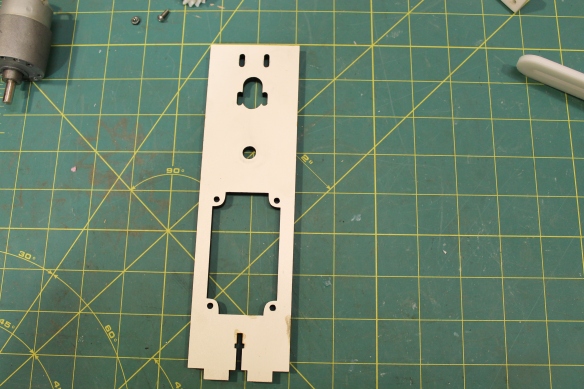
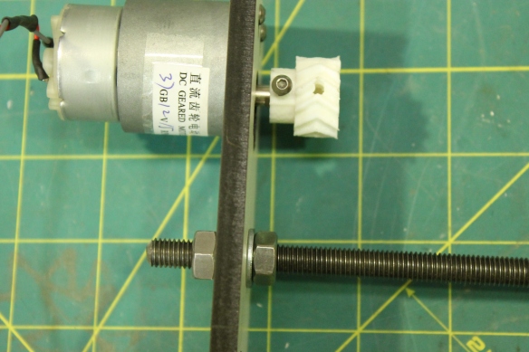
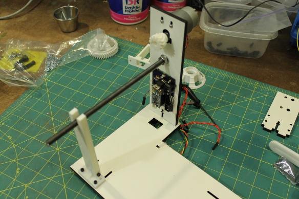
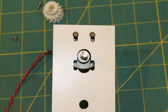 Use 2 M3x12 to mount the gear motor in the slots at the top of the long piece of wood. Leave them just loose enough to slide the motor up and down.
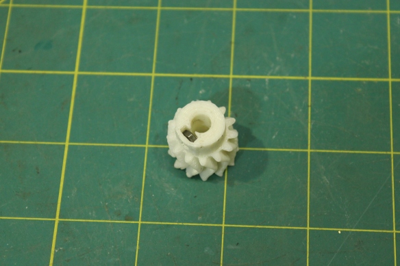
Slide a M3 nut into the nut trap in the drive gear.
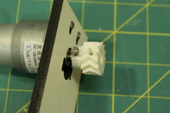
Put the drive gear on the motor shaft and screw the third M3x12 through the nut to hold it tight on the shaft.
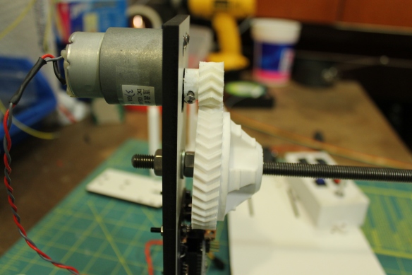
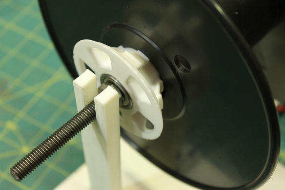
Put the threaded rod through the hole under the motor with a nut and a washer on each side.
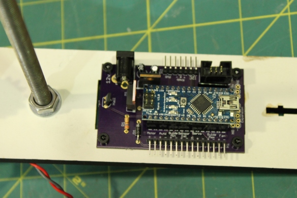
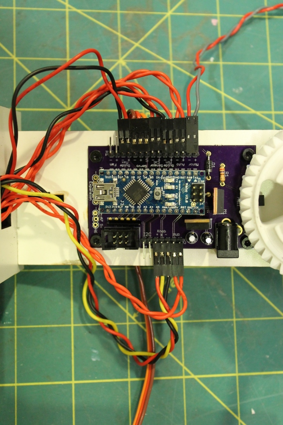
Bolt the electronics directly to the wood with 4 M3x16 screws. The USB port should be at the bottom.
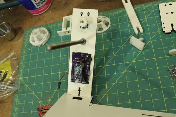
Set the wood into the slots at the back of the base.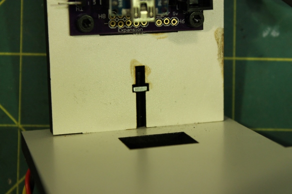
Use a M3x25 bolt and a square washer in the t-slot to hold the pieces of wood tightly together.
Use 2 M3x16 screws to mount the support base in the slots across from the motor mount.
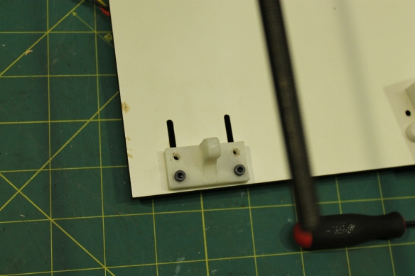
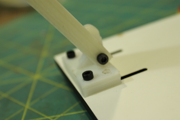
Use a M3x25 screw to attach the support arm to the hinge. Make sure the curved edge of the arm faces the edge of the board so the arm is free to rotate away from the spool.
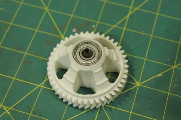
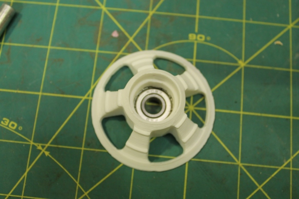
Put a 608 bearing into both sides of the large gear.
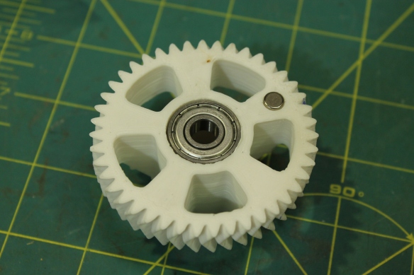
In addition to the bearing, put the magnet into the 1/4″ hole on the flat side of the large gear. The north pole of the magnet should face out. If you leave the magnet on its side on a table and flick it a couple of times, it will spin and stop with the north pole facing to the north.
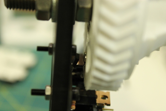
Lift the motor to the top of its mounting slots to move the drive out of the way, then slide the large gear on to the threaded rod. The magnet should pass close to the hall sensor when you turn the gear.
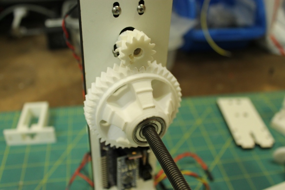
Loosen the set screw in the drive gear and adjust its position until it lines up with the large gear.
Slide the motor down until the drive gear fully engages the large gear, then tighten the bolts in the slots.
Put a 608 bearing into the flat side of the spool hub.
Slide a spool on to the threaded rod and use the spool hub to hold it tight against the large gear. Tighten a nut against the spool bearing to hold it in place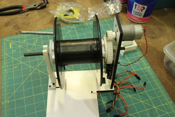
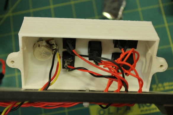
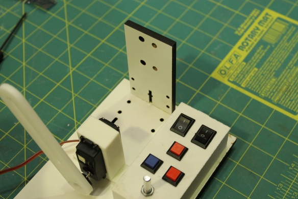
Each of the wires has a crimp at each end. Cut the wires in half, strip the cut ends, and solder them to the terminals of the potentiometer, buttons, and switches. Push the crimped ends into the 2×1 housings for the switches and buttons, and into the 3×1 housing for the potentiometer. Snap the buttons and switches into the control box and mount the potentiometer using the thin hex nut on the shaft. Mount the control box to the left edge of the base using M3x16 screws. The wires can run through the hole under the control box, under the base, and up through the hole below the control board. There is also a notch in the hole under the control box that would allow the wires to run out over the top of the base if that is preferred. There is a hole in the base near the right edge near the board that holds the motor. This can be used as a place to run a zip tie to hold the bundled wires against the base.
Plug the wires for the right button into Guide Min, the left button into Guide Max, and the center button into Sensor Calon the left edge of the control board. The wire from the left switch goes into Auto on the left side of the board, and the right switch goes to Power on the right side of the board. Plug the potentiometer in to Knob on the right side of the board. Solder a shorter pair of wires to the motor and push the crimps into a 2×1 housing, then plug it into the Motor headers at the top left of the board. To change the direction of the motor, flip the plug over.
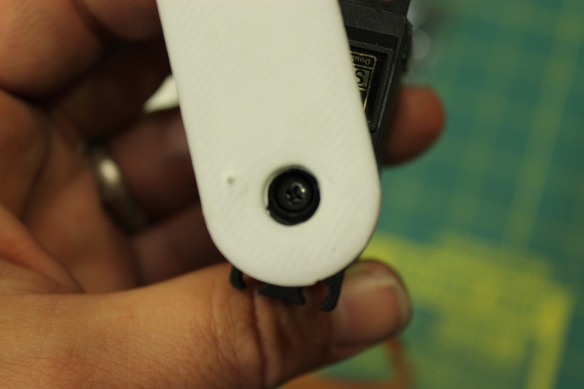
Use the small sharp screws that come with the servo to attach the guide arm to the servo’s disc. You might need to drill some small pilot holes in the arm. Put the disc on to the servo’s hub, and move the arm back and forth to check that each end of the rotation puts the arm horizontal, and at the halfway point the arm points up. Use the black screw in the servo kit to secure the disc to the hub.
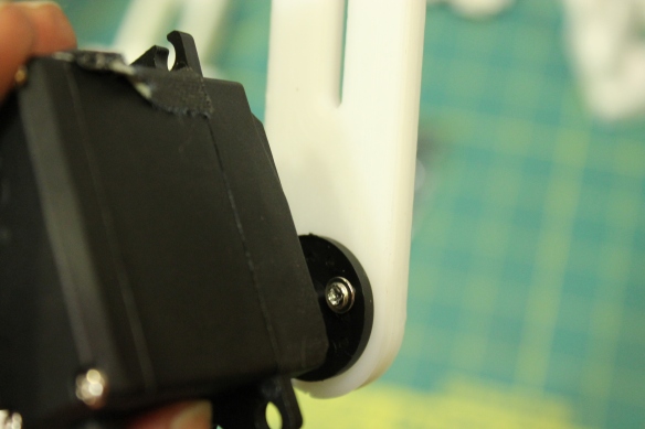
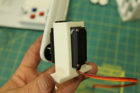
Slide the servo in to the servo mount. If the fit is a little loose, you can wrap some tape around the servo to make it more snug. Use m3x16 screws to mount the servo in to the slots next to the control box. Plug the servo in where it says Servo on the left edge of the control board, with the brown wire at the bottom.
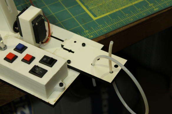
The filament intake can be mounted vertically or horizontally. Mount it vertically if the base of the wider will be mounted to the wall, or otherwise positioned vertically.
Use M3x16 screws to mount the board horizontally if the winder will lay flat, as on a shelf. Loop 12″ of 4mm OD PTFE tube into the smaller, bottom hole from below, and back through the upper hole from below as well. The filament will pass through the tube and create enough drag to provide adequate tension to the spool. The larger pair of holes is for 6mm OD PTFE tube to accommodate 3mm filament.
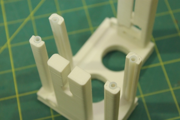
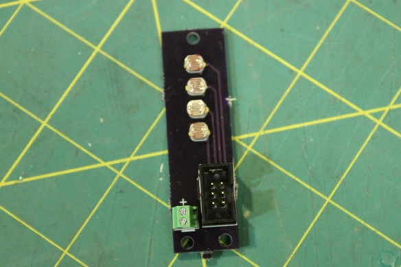
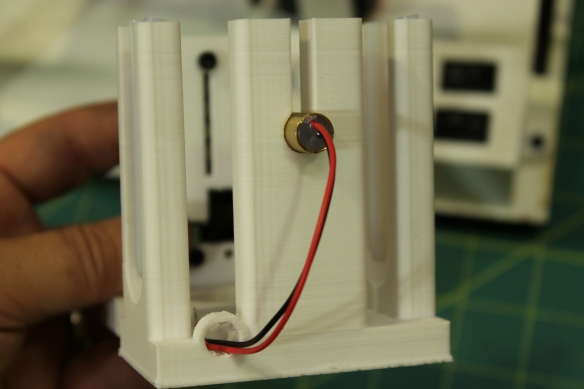
Slide the short sections of tubing into the channels in the filament guides on the laser mount. Take care not to break the guides. Put the laser into the laser mount, and run the wires through the channel in the base. Using a tiny screwdriver, secure the wires in the terminal block on the sensor board, with the red wire on top.
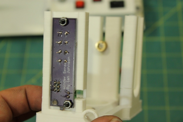
Using 2 M3x16 screws, mount the sensor board with the photocells facing the slot.
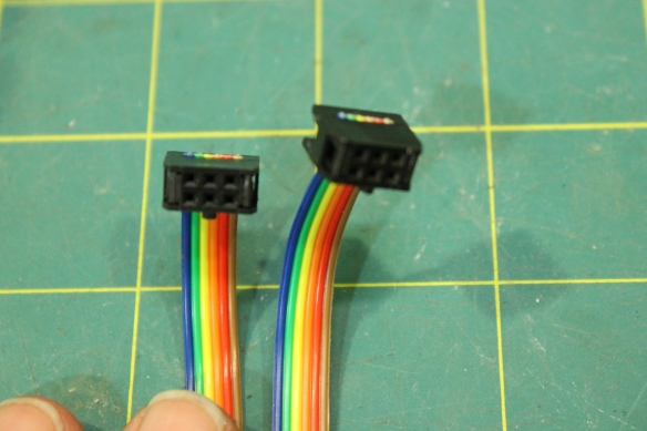
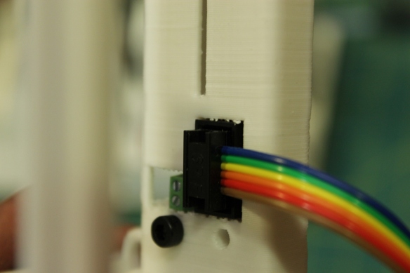
Add crimps to the ribbon cable. Slide the cable into the crimp from the side that has the notch. Orient the cable the same way for both crimps. Squeeze the crimp closed using a vice to apply even pressure, then trim away any excess wire.
Plug one end into the sensor board, and the other end into the control board.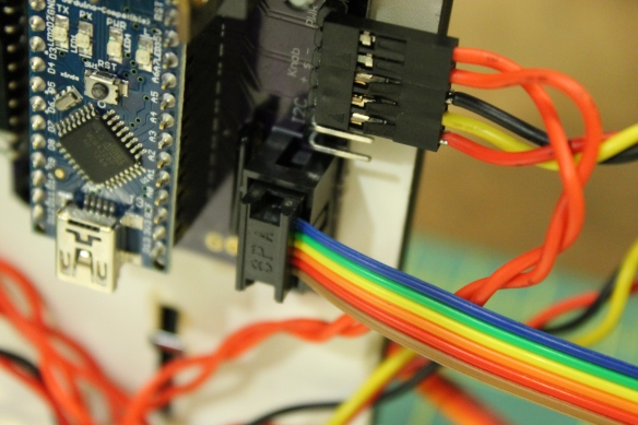
Turn on the right switch for power. The left switch changes between Manual mode, where the speed of the spool is controlled by the knob. and Auto mode, where the speed is controlled by the sensor. Press and hold the left button and turn the knob to position the guide arm at the left limit, to set the furthest point the guide will travel in that direction. Press and hold the right button and turn the knob to position the guide arm at the right limit . When in Auto mode, holding the middle button will allow the knob to change the current position of the guide. The direction the guide traveled to reach that position will be the direction it continues to move as the spool turns.
When in Manual mode, the middle button calibrates the sensors. When the button is pushed, the winder will go into calibration mode for 5 seconds. During this time pass a piece of filament back and forth between the filament guides to cast a shadow over all of the sensors. The winder will record the darkest and lightest values during those 5 seconds and determine what is shadow and what is ambient light.
After calibration, you can test the sensor by waving a piece of filament over it while in Auto mode. The motor should speed up when the filament drops below the middle sensors, and slow down as the filament rises.

Pingback: The FilaWinder